41
Chapter 3: Testing Performance
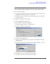
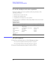
To test the single-clock, single-edge, state acquisition
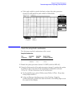
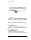
c If the pulse width is outside the limits, adjust the pulse generator
channel 2 width until the pulse width is within limits.
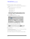
Check the setup/hold combination
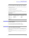
The following setup/hold combinations will be tested:
Setup/Hold Combinations
1 Disable the pulse generator channel 1 COMP (with the LED off).
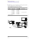
2 Using the Delay mode of the pulse generator channel 1, position the pulses
according to the setup time of the setup/hold combination selected,
+0.0 ps or −100 ps as measured on the oscilloscope:
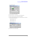
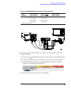
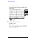
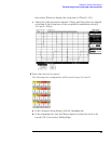
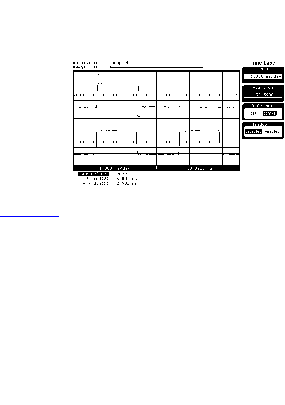
a On the Oscilloscope, select [Define meas] Define ∆ Time - Stop edge:
rising, Edge number 2.
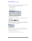
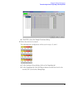
b In the oscilloscope timebase menu, select Position. Using the
oscilloscope knob, position the data waveform so the falling edge is near
the center of the display.
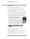
Te s t
Combination
Setup/Hold
Times
Setup/Hold
Window
Sample Position
(in middle of Window)
1 4.50/-2.0 ns 2.5 ns -3.25 ns
2 -2.0/4.50 ns 2.5 ns +3.25 ns


