


22
Chapter 3: Testing Performance
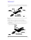
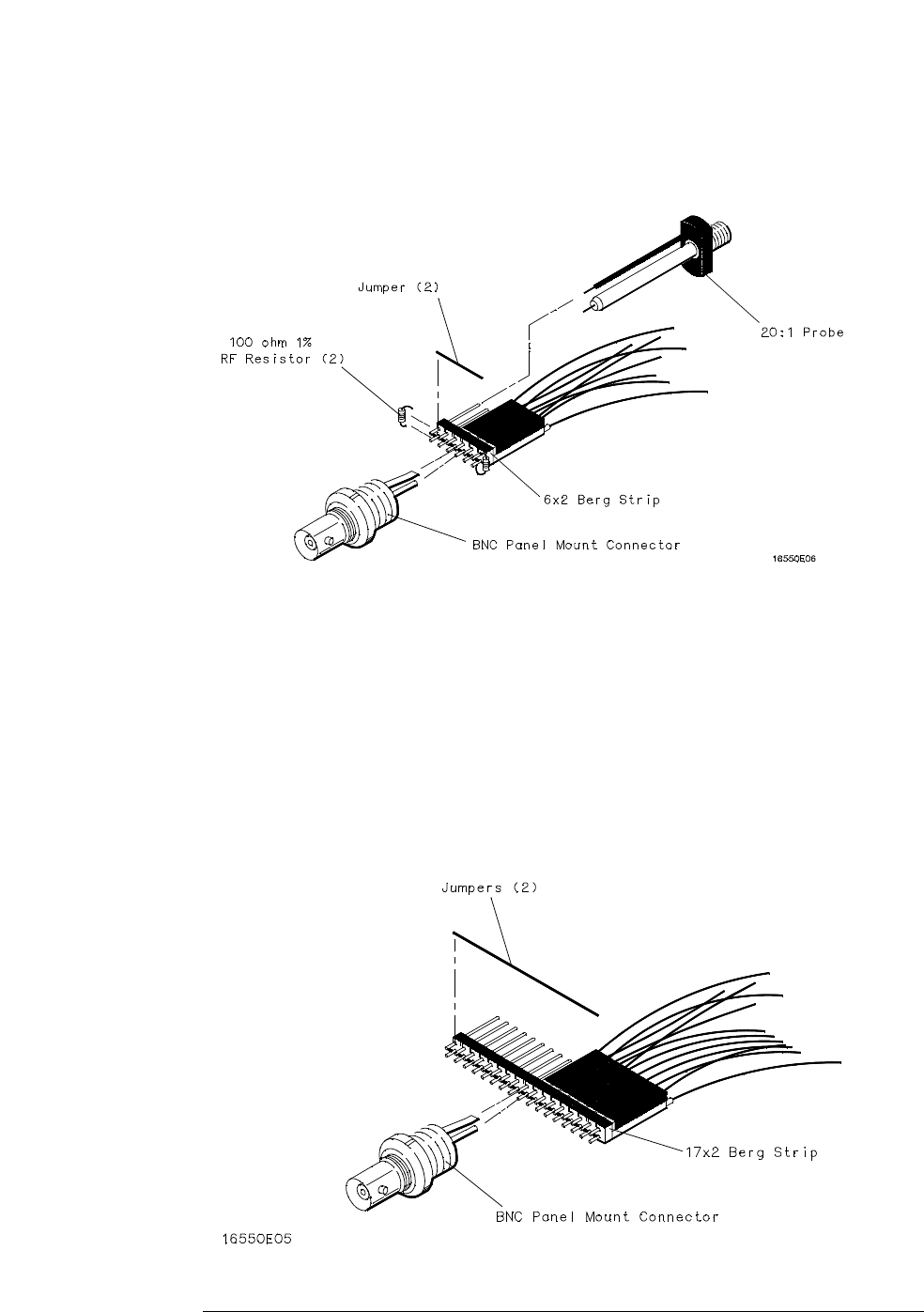
To make the test connectors
f On two of the test connectors, solder a 20:1 probe. The probe ground
goes to the same row of pins on the test connector as the BNC ground
tab.
2 Build one test connector using a BNC connector and a 17-by-2 section of
Berg strip:
a Solder a jumper wire to all pins on one side of the Berg strip.
b Solder a jumper wire to all pins on the other side of the Berg strip.
c Solder the center of the BNC connector to the center pin of one row on
the Berg strip.
d Solder the ground tab of the BNC connector to the center pin of the
other row on the Berg strip.