


110
Chapter 5: Troubleshooting
General Troubleshooting
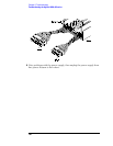
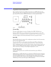
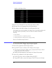
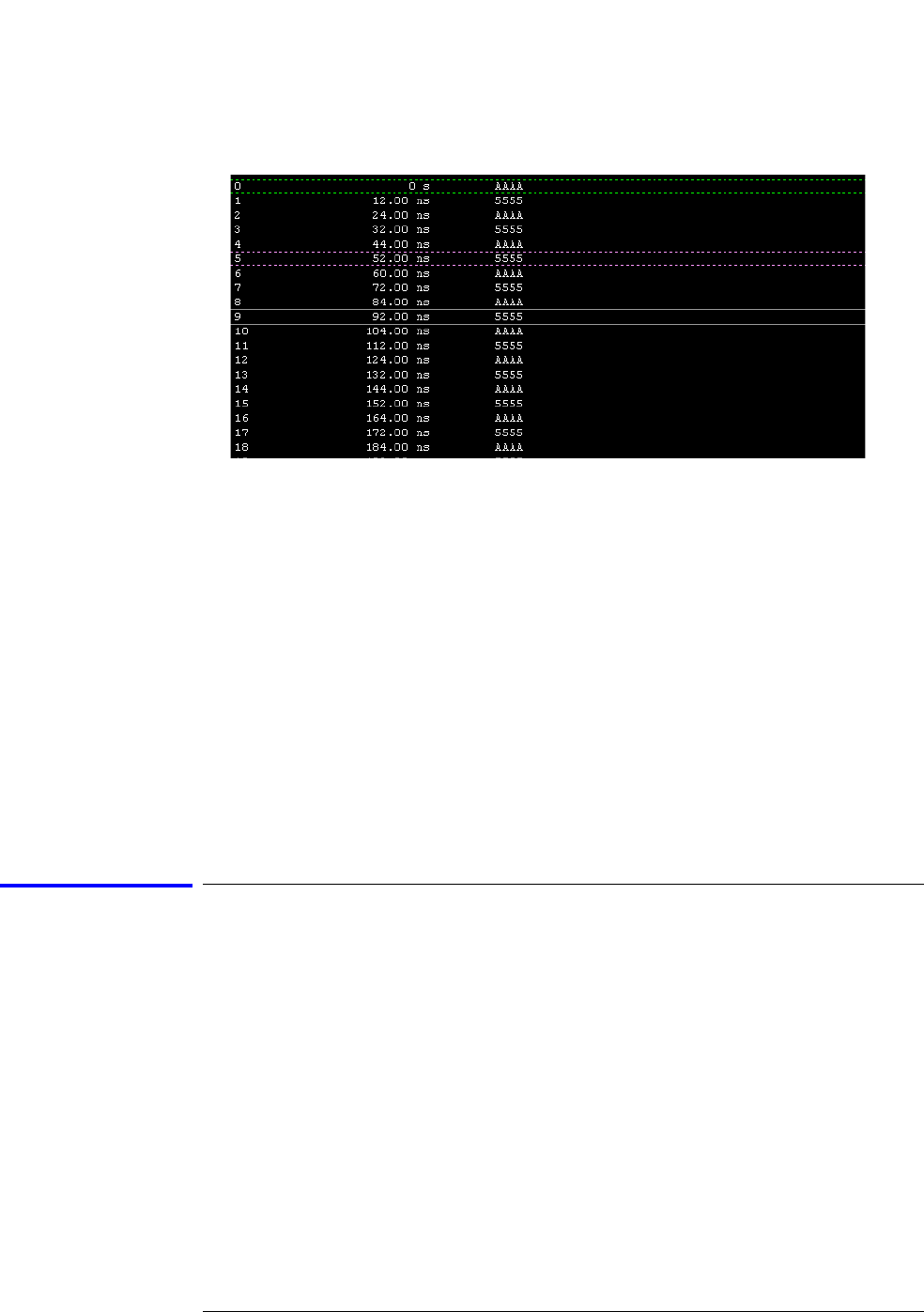
similar to the figure below.
7 Repeat steps 3 through 7 to test other logic analyzer cables.
8 Disconnect the test equipment from the logic analyzer.
9 If the display looks like the figure, the cable passed the test.
If the display does not look similar to the figure, there is a possible problem with
the cable or probe tip assembly. Causes for cable test failures include the
following:
• Open channel.
• Channel shortened to a neighboring channel.
• Channel shortened to either ground or a supply voltage.
Return to Troubleshooting flowchart 7.
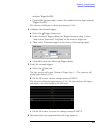
To check the BNC Trigger input/output signals
1 Turn on the equipment and the logic analyzer.
2 Set up the DC source to deliver a DC voltage on the output:
a In the function generator Utility menu, activate the DC Level. All AC
voltage functions will be disabled.
b Enable the high impedance load under the Output Setup menu.
3 Connect the equipment to the logic analyzer:
a On the DC source, enter a voltage setting of 0.000 V.
b Using a BNC cable, connect the output of the DC Source to the logic