


24 System Connections
PCS-G70/G70P
3-863-237-11 (1)
Y:\04C08060_passage\EDIT\03OVR.FM
masterpage:Left
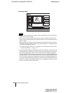
• Do not connect/disconnect the camera cable or the interface cable with the power on.
Doing so may damage the Camera Unit, Communication Terminal or ISDN Unit.
• Used with an ISDN Unit for the first time, the Communication Terminal may
automatically upgrade the software of the ISDN Unit. While the upgrading message
is displayed on the monitor screen, be sure not to turn off the Communication
Terminal. Doing so may cause malfunction of the system.
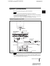
• If you are only using one camera, be sure to connect it to the MAIN CAMERA connector.
• The AUDIO OUT (MIXED) jack is used to make an audio recording of a conference.
This is not used during regular conferences.
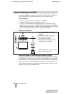
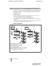
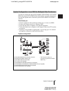
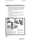
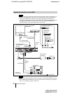
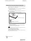
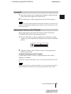
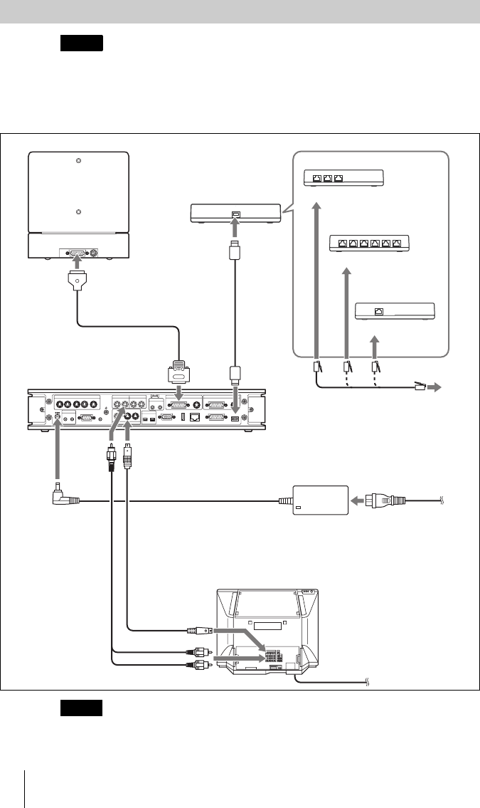
System Connection via an ISDN
Notes
Notes
TERMINAL VISCA OUT
(MIXED)
AUX
AUX
MONITOR
LINE
AUX CONTROL
MCU VIDEO OUT
VIDEO OUT
AUDIO OUT AUDIO IN
MIC
MAIN SUB
EC-MIC
CTRL-S
RGB OUT DSB
ISDN UNIT
IR OUT
12
1234
12
12
12
5
DC 19.5V
CAMERA CAMERAAUX IN AUX IN
WHITE
BOARD
100BASE-TX/
10BASE-T
(PLUG IN POWER)
PCSA-CG70/CG70P
Camera Unit
to TERMINAL
PCS-PG70/PG70P
Communication
Terminal
Camera cable*
Audio cable*
S-video
cable*
Power cord*
to MAIN
CAMERA
to
AUDIO
OUT
to VIDEO OUT
MONITOR 1
to
S-video
input
to audio input
TV monitor**
to a wall outlet
* supplied
**not supplied
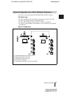
Interface cable (supplied
with ISDN UNIT)
to ISDN
UNIT
to TERMINAL
PCSA-B384S ISDN Unit**
to ISDN 1-6
ISDN Unit
**
to ISDN 1-3
ISDN modular cable**
PCSA-B768S
ISDN Unit**
PCS-AC19V6
AC adaptor
PSCA-PRI
ISDN Unit**
to a wall outlet
to DC19.5V
to ISDN PRI