


PCS-G70/G70P
3-863-237-11 (1)
Y:\04C08060_passage\EDIT\07OPE.FM
masterpage:Left
143Connection Example Using the Data Solution Box
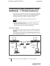
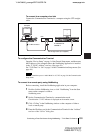
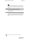
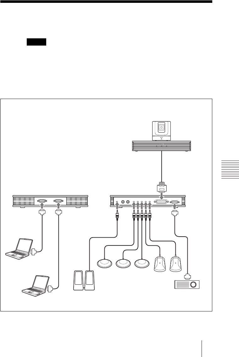
Connection Example Using the Data
Solution Box
• Be sure not to turn on the power of each unit until all the connections are completed.
• Do not connect/disconnect the camera cable or the interface cable with the power on.
Doing so may damage the Camera Unit, Communication Terminal or Data Solution
Box.
• Used with the Data Solution Box for the first time, the Communication Terminal may
automatically upgrade the software of the Data Solution Box. While the upgrading
message is displayed on the monitor screen, be sure not to turn off the Communication
Terminal. Doing so may cause malfunction of the system.
Notes
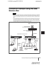
AUX MIC 1 MIC 2 MIC 3 MIC 4 MIC 5 TO PROCESSOR RGB OUTOUTLINE OUT IN
to DSB
Rear
PCSA-CG70/CG70P Camera
Unit
Front
PCS-PG70/PG70P
Communication Terminal
to RGB IN A
D-sub 15-
pin cable
(not
supplied)
Interface cable (supplied with
the PCSA-DSB1S)
to RGB
IN B
D-sub 15-pin
cable
(not supplied)
Computer
Computer
to TERMINAL
to LINE
OUT
Active speakers
to MIC 1
– MIC 5
PCS-A1 (not supplied) or
PCS-A300 microphone (not
supplied)
to RGB OUT
D-sub 15-pin
cable (not
supplied)
Projector, etc.
PCSA-DSB1S Data Solution Box