


PCS-G70/G70P
3-863-237-11 (1)
Y:\04C08060_passage\EDIT\10OTH.FM
masterpage:Left
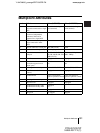
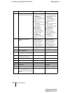
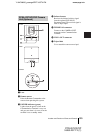
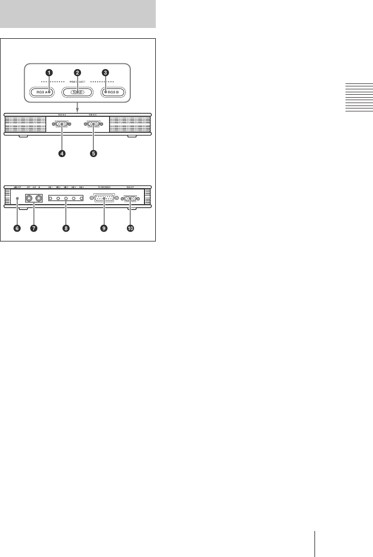
199Location and Function of Parts and Controls
a RGB A input select button and
indicator
Selects the video input from the video
equipment connected to the RGB IN A
connector.
b SEND button and indicator
Sends the selected input picture to the
Communication Terminal.
c RGB B input select button and
indicator
Selects the video input from the video
equipment connected to the RGB IN B
connector.
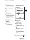
d RGB IN A connector (D-sub 15-pin)
Connects to the RGB output connector
on a computer, etc.
e RGB IN B connector (D-sub 15-pin)
Connect to the RGB output connector on
a computer, etc.
f LINE OUT jack (stereo minijack)
Connect to the audio input jack on the
active speaker, etc.
Outputs monaural sound.
g AUX IN/OUT jacks (phono jack)
Connects to the optional CTE-600
Communication Transducer.
h MIC 1–MIC 5 jacks (minijack)
Connect to the optional PCS-A1 or PCS-
A300 microphone.
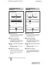
i TO PROCESSOR connector (D-sub
15-pin)
Connect to the DSB connector on the
Communication Terminal using the
interface cable supplied with the Data
Solution Box.
j RGB OUT connector (D-sub 15-
pin)
Outputs the video signal to a projector,
TV monitor, etc.
PCSA-DSB1S Data Solution
Box (Optional)
Front/Upper panel
Rear