


PCS-G70/G70P
3-863-237-11 (1)
Y:\04C08060_passage\EDIT\10OTH.FM
masterpage:Left
193Location and Function of Parts and Controls
Location and
Function of Parts
and Controls
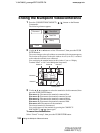
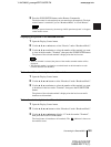
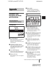
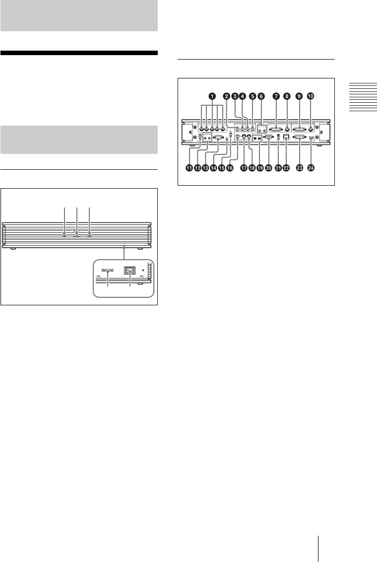
Front/Right side
a ON LINE indicator
Blinks during dialing or answering and
lights in blue when connection is
completed. It turns off when the system
is disconnected.
b POWER/STANDBY indicator
Lights in green when the power switch is
set to on (@). Lights in orange when the
Communication Terminal is set to
standby mode.
c LAN ALERT indicator
Lights in yellow when packet error (loss) or
link error occurs during communication.
d Memory Stick slot
Insert a “Memory Stick” (not supplied)
into this slot.
e Power switch
Turns on/off the Communication
Terminal. The power is on when the
switch is set to the @ side and off when
the switch is set to the a side.
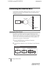
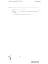
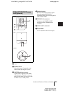
Rear
a MCU VIDEO OUT (1 - 5)
connectors (mini DIN 4-pin)
During a multipoint conference, the
video signal from each point is output to
the corresponding connector.
b
AUDIO OUT (MIXED) jack (phono jack)
Used when recording the sound to
minute a conference. The mixed sounds
of a local and remote parties are output
from this jack.
c AUDIO OUT jack (phono jack)
Connect to the audio input of the TV
monitor.
d AUDIO IN AUX jack (phono jack)
Connect to the audio output of the
optional VCR or audio equipment.
e AUDIO IN LINE jack (phono jack)
Used when connecting to the optional
CTE-600 Communication Transducer or
an external microphone mixer.
f MIC1/MIC2 (PLUG IN POWER)
jacks (minijack)
Connect to the optional PCS-A1 or PCS-
A300 microphone. Power is supplied to
the microphone from the
Communication Terminal.
Appendix
PCS-PG70/PG70P
Communication Terminal
123
45
(MIXED)
AUX
AUX
MONITOR
LINE
AUX CONTROL
MCU VIDEO OUT
VIDEO OUT
AUDIO OUT AUDIO IN
MIC
MAIN SUB
EC-MIC
CTRL-S
RGB OUT DSB
ISDN UNIT
IR OUT
12
1234
12
12
12
5
DC 19.5V
CAMERA CAMERAAUX IN AUX IN
WHITE
BOARD
100BASE-TX/
10BASE-T
(PLUG IN POWER)