


PCS-G70/G70P
3-863-237-11 (1)
Y:\04C08060_passage\EDIT\10OTH.FM
masterpage:Left
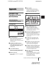
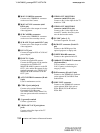
195Location and Function of Parts and Controls
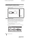
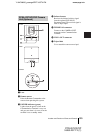
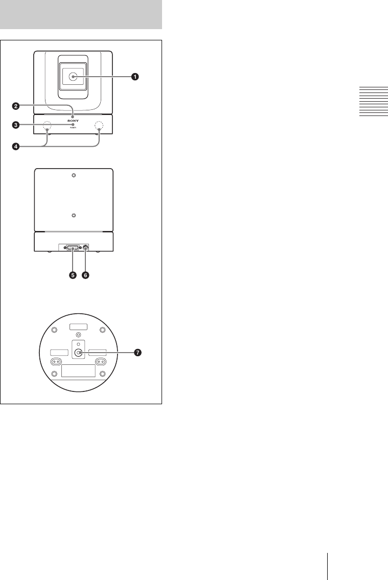
a Lens
b Remote sensor
Point the Remote Commander to the
sensor when operating this system.
c POWER indicator (green)
Lights when the power switch on the
Communication Terminal is set to on
and goes out when it is set to off or the
terminal is set to standby mode.
d Infrared sensor
Receives the infrared wireless signal
from the optional PCS-DS150
Document Stand. The received signal is
used as object input.
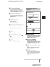
e TERMINAL connector
Connect to the CAMERA UNIT
connector on the Communication
Terminal.
f VISCA OUT connector
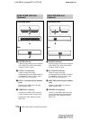
g Tripod hole
Use to attach the camera on a tripod.
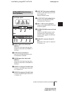
PCSA-CG70/CG70P Camera
Unit (Optional)
TERMINAL VISCA OUT
Front
Rear
Bottom