


218 Specifications
PCS-G70/G70P
3-863-237-11 (1)
Y:\04C08060_passage\EDIT\10OTH.FM
masterpage:Left
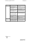
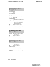
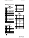
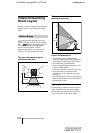
TERMINAL connector
D-sub 15-pin connector (female)
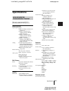
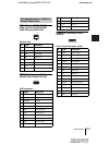
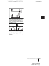
DSB connector
D-sub 15-pin (male)
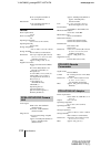
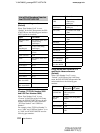
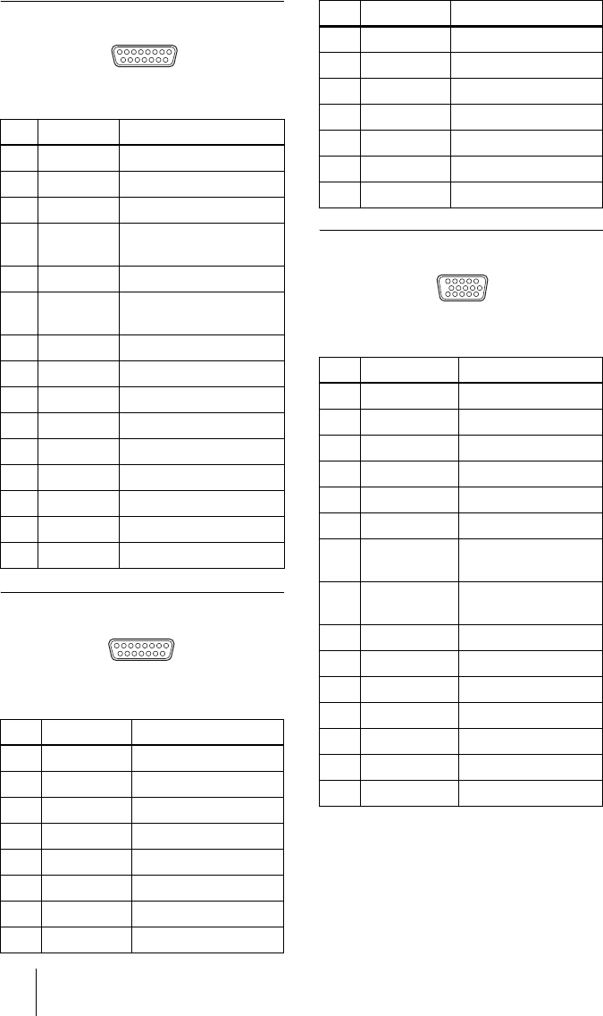
RGB OUT connector
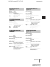
Mini D-sub 15-pin (female)
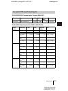
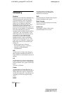
Pin Signal Description
1 Y Brightness signal
2 Y.GND Brightness signal ground
3 C Chrominance signal
4 C.GND Chrominance signal
ground
5 Video Video signal
6Video.GN
D
Video signal Ground
7 RXD Receive data
8 TXD Transmit data
9 19.5 V 19.5 V
10 MIC+ Microphone+
11 MIC– Microphone–
12 SIRCS Remote control data
13 DTR Data terminal ready
14 STANDBY Standby
15 GND Ground
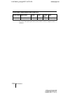
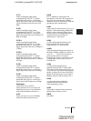
Pin Signal Description
1 Video Video signal
2 Video.GND Video signal ground
3 LINE A+ Line audio+
4 LINE A– Line audio–
5 MIC+ Microphone+
6 MIC– Microphone–
7 TD+ Receive+
8 TD– Receive–
15 9
81
9 15
18
9 19.5V 19.5V
10 NC –
11 AGND Analog ground
12 NC –
13 RD+ Transmit data+
14 RD– Transmit data–
15 GND Ground
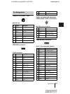
Pin Signal Description
1 RED R (red)
2 GREEN G (green)
3BLUE B (blue)
4NC –
5 GND Ground
6 RED.GND R (red) signal ground
7 GREEN.GND G (green) signal
ground
8 BLUE.GND B (blue) signal
ground
9NC –
10 SYNC.GND Sync signal ground
11 NC –
12 NC –
13 HSYNC Horizontal sync
14 VSYNC Vertical sync
15 NC –
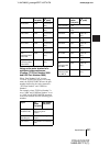
Pin Signal Description
15 11
51
10 6