


PCS-G70/G70P
3-863-237-11 (1)
Y:\04C08060_passage\EDIT\10OTH.FM
masterpage:Left
197Location and Function of Parts and Controls
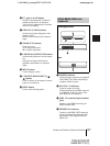
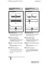
j @/1 (power on/off) button
Sets the Communication Terminal to
standby mode when it is turned on.
Turns on the Communication Terminal
when it is in standby.
k DISPLAY (CLEAR) button
Switches the picture displayed on the
monitor screen.
Deletes a line when used for character
input.
l ZOOM (T/W) buttons
Zooms in or out.
T: to enlarge the picture
W: to reduce the picture
m FAR/NEAR (ALPHA/NUM) button
Switches the picture on a local or remote
site.
Switches the input mode between
alphabets and numbers for character
input.
n MENU button
Used to display a menu.
o CONNECT/DISCONNECT ( /
) button
Used to connect or disconnect a remote
party for a conference.
p HELP button
Used to show the help guide.
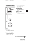
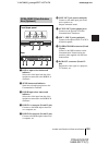
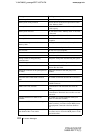
a POWER indicator
Lights in orange when power is supplied
to the ISDN Unit. When initializing is
complete, blinks in green.
b STATUS 1-3 indicators
Lights in orange when link
synchronization of each ISDN connector
is established. Lights in yellow when
each ISDN line is connected.
c ISDN 1-3 terminals (8-pin modular
jack)
Connect to the ISDN lines using the
ISDN modular cable.
d TERMINAL connector
Connect to the ISDN UNIT connector
on the Communication Terminal with
the interface cable supplied with the
ISDN Unit.
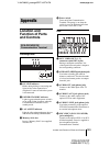
PCSA-B384S ISDN Unit
(Optional)
Front/Upper panel
Rear