


PCS-G70/G70P
3-863-237-11 (1)
Y:\04C08060_passage\EDIT\10OTH.FM
masterpage:Left
217Specifications
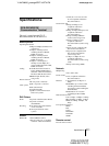
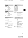
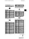
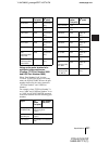
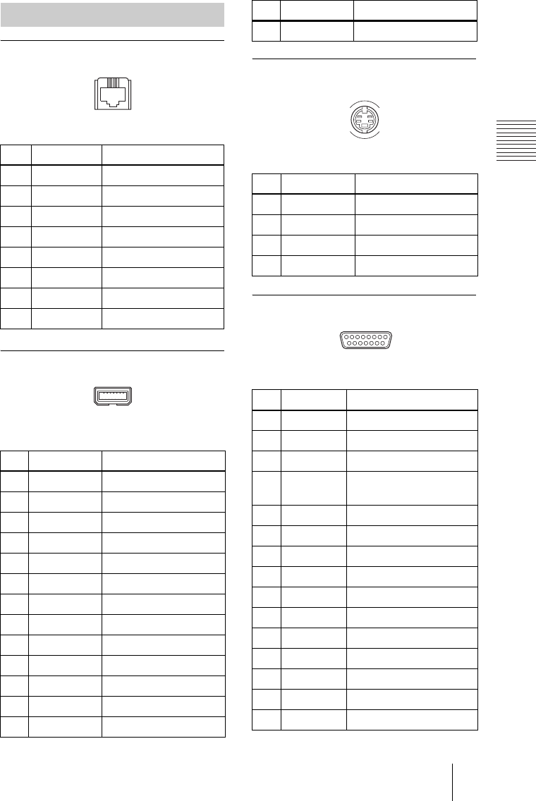
100BASE-TX/10BASE-T jack
Modular jack
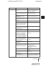
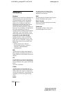
ISDN UNIT connector
14-pin connector
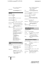
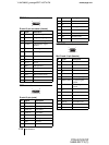
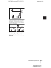
VIDEO OUT MONITOR MAIN/SUB,
VIDEO IN AUX 1/AUX 2 connectors
Mini-DIN 4-pin connector
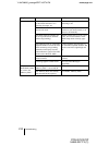
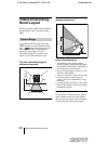
CAMERA UNIT connector
D-sub 15-pin connector (female)
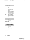
Pin Assignments
Pin Signal Description
1TPOP Transmit+
2TPON Transmit–
3 TPIP Receive+
4NC —
5NC —
6 TPIN Receive–
7NC —
8NC —
Pin Signal Description
1 GND Ground
2 19.5V 19.5V
3DCLK+ Clock+
4DCLK– Clock–
5 DR+ Receive data+
6 DR– Receive data–
7 FS+ Frame sync+
8 FS– Frame sync–
9 DX+ Transmit data+
10 DX– Transmit data–
11 RX Serial receive data
12 TX Serial transmit data
13 19.5V 19.5V
18
113
214
14 GND Ground
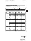
Pin Signal Description
1 GND Analog Ground
2 GND Analog Ground
3 Y Brightness Signal
4 C Chrominance Signal
Pin Signal Description
1 Y Brightness signal
2 Y.GND Brightness signal ground
3 C Chrominance signal
4 C.GND Chrominance signal
ground
5 Video Video signal
6 Video.GND Video signal Ground
7 TXD Transmit data
8 RXD Receive data
9 19.5 V 19.5 V
10 MIC+ Microphone+
11 MIC– Microphone–
12 SIRCS Remote control data
13 DTR Data terminal ready
14 STANDBY Standby
15 GND Ground
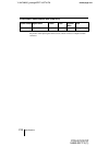
Pin Signal Description
4
2
3
1
15 9
81