


PCS-G70/G70P
3-863-237-11 (1)
Y:\04C08060_passage\EDIT\03OVR.FM
masterpage:Left
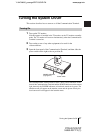
23System Connections
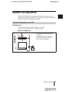
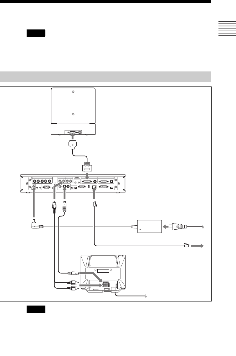
System Connections
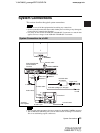
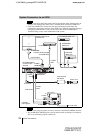
This section describes the typical system connections.
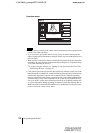
• Be sure to turn off all the equipment before making any connections.
• Do not connect/disconnect the camera cable with the power on. Doing so may damage the
Camera Unit or Communication Terminal.
• For safety, do not connect the 100BASE-TX/10BASE-T connector to a network that
applies an excess voltage via the 100BASE-TX/10BASE-T connector.
• If you are only using one camera, be sure to connect it to the MAIN CAMERA connector.
• The AUDIO OUT (MIXED) jack is used to make an audio recording of a conference.
This is not used during regular conferences.
Notes
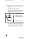
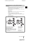
System Connection via a LAN
Notes
TERMINAL VISCA OUT
(MIXED)
AUX
AUX
MONITOR
LINE
AUX CONTROL
MCU VIDEO OUT
VIDEO OUT
AUDIO OUT AUDIO IN
MIC
MAIN SUB
EC-MIC
CTRL-S
RGB OUT DSB
ISDN UNIT
IR OUT
12
1234
12
12
12
5
DC 19.5V
CAMERA CAMERAAUX IN AUX IN
WHITE
BOARD
100BASE-TX/
10BASE-T
(PLUG IN POWER)
PCSA-CG70/CG70P Camera Unit
to TERMINAL
PCS-PG70/PG70P
Communication
Terminal
Camera cable*
S-video cable*
Power cord*
to MAIN CAMERA
to
AUDIO
OUT
to
VIDEO OUT
MONITOR 1
to
S-video
input
to audio input
to 100BASE-TX/
10BASE-T
to LAN
TV monitor**
to a wall outlet
to DC19.5V
PCS-AC19V6
AC adaptor
to a wall outlet
* supplied
**not supplied
UTP cable (category 5, straight)**
Audio cable*