


Groundsmaster 4000--D/4010--D Hydraulic SystemPage 4 -- 49
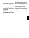
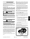
Procedure for Reverse Traction Circuit
Reducing
Valve (PR) Pressure
Test
NOTE: When in reverse, pressure reducing valve (PR)
limits the pressure to the rear axle motor to 380 PSI (26
bar) so the rear wheels will not scuff the turf.
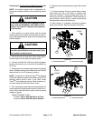
CAUTION
Prevent personal injury and/or damage to equip-
ment. Read all WARNINGS, CAUTIONS and Pre-
cautions for Hydraulic Testing at the beginning
of this section.
1. Park machine on a level surface with the cutting
decks lowered and off. Make sure hydraulic oil is at nor-
mal operating temperature, engine isoff and theparking
brake is applied.
NOTE: The #6 zero leak plug on the inside of rear trac-
tion m a nifold is a zero leak plug that has a tapered seal-
ing surface on the plug head. Lightly rap the plug head
using a punch and hammer before using an allen
wrench to remove the plug: the impact will allow plug re-
moval with less chance of damage to the socket head of
the plug.
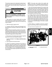
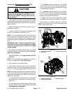
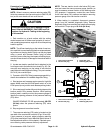
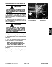
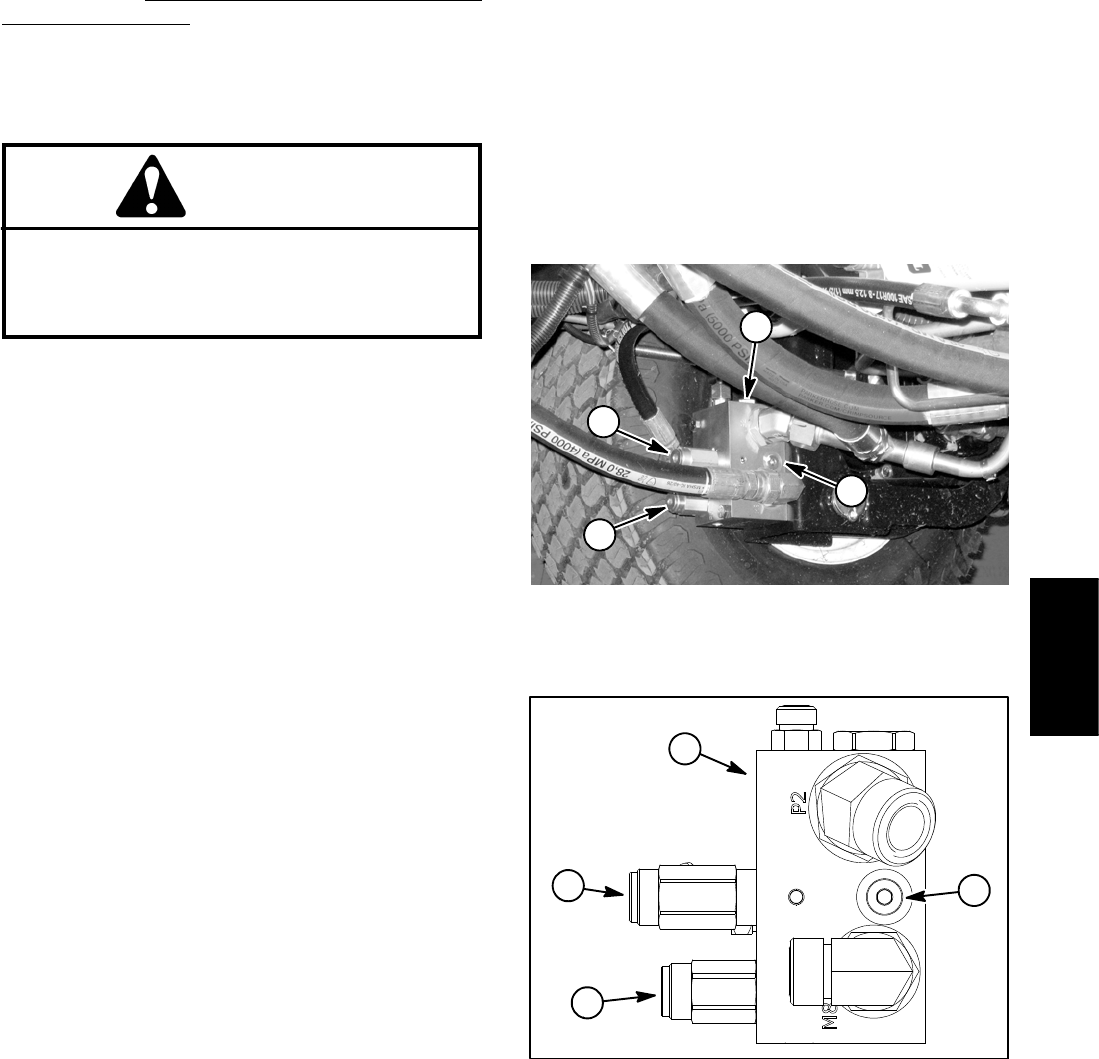
2. Locate rear traction manifold t hat is attached to the
front frame next to the left side front wheel (Fig. 32). Re-
move #6 zero leak plug on the inside of rear traction
manifold and install diagnostic fitting (Toro part number
59--7410) into manifold port.
3. Connecta1000 PSI(70 bar)pressure gaugewithhy-
draulic hose attached to installed diagnostic fitting.
4. Start engine and increase engine speed to high idle
speed. Make sure that HI/LOW speed switch is in the
LOW speed (mow) position and release parking brake.
5. Sit on seat, apply brakesfully and slowly depress the
traction pedal in the reverse direction. While pushing
traction pedal, carefully monitor the pressure gauge to
identify the opening pressure of the pressure reducing
(PR) valve:
GAUGE READING TO BE approximately 380 PSI
(26 bar) when the pressure reducing (PR) valve
opens.
6. Stop engine and record test results.
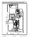
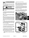
7. The pressure reducing (PR) valve is located on the
rear side of the rear traction manifold (Figs. 32 and 33).
If test pressure is incorrect, adjust pressure reducing
(PR) valve (see Adjust Control Manifold Relief Valves in
the Adjustments section of this chapter). Recheck pres-
sure reducing valve pressure after any adjustment.
NOTE: The rear traction circuit relief valve (RV) pres-
sure test uses the same pressure gauge position as
used to measure reverse traction circuit reducing valve
(PR) pressure. If necessary, conduct the rear traction
circuit relief valve (RV) pressure test before removing
pressure gauge from rear traction manifold.
8. When testing is completed, disconnect pressure
gauge from the installed diagnostic fitting. Remove
diagnostic fitting from manifold and install removed plug
into manifold. Torque plug to 25 ft--lb (34 N--m).
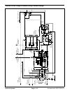
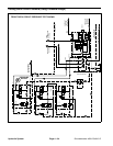
1. Rear traction manifold
2. #6 z ero leak plug
3. Relief(RV)valve
4. Reducing (PR) valve
Figure 32
2
1
3
4
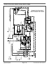
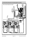
1. Rear traction manifold
2. #6 z ero leak plug
3. Relief(RV)valve
4. Reducing (PR) valve
Figure 33
1
2
3
4
Hydraulic
System