


Groundsmaster 4000--D/4010--D Hydraulic SystemPage 4 -- 27
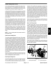
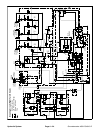
Engine Cooling Fan Circuit
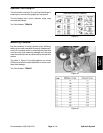
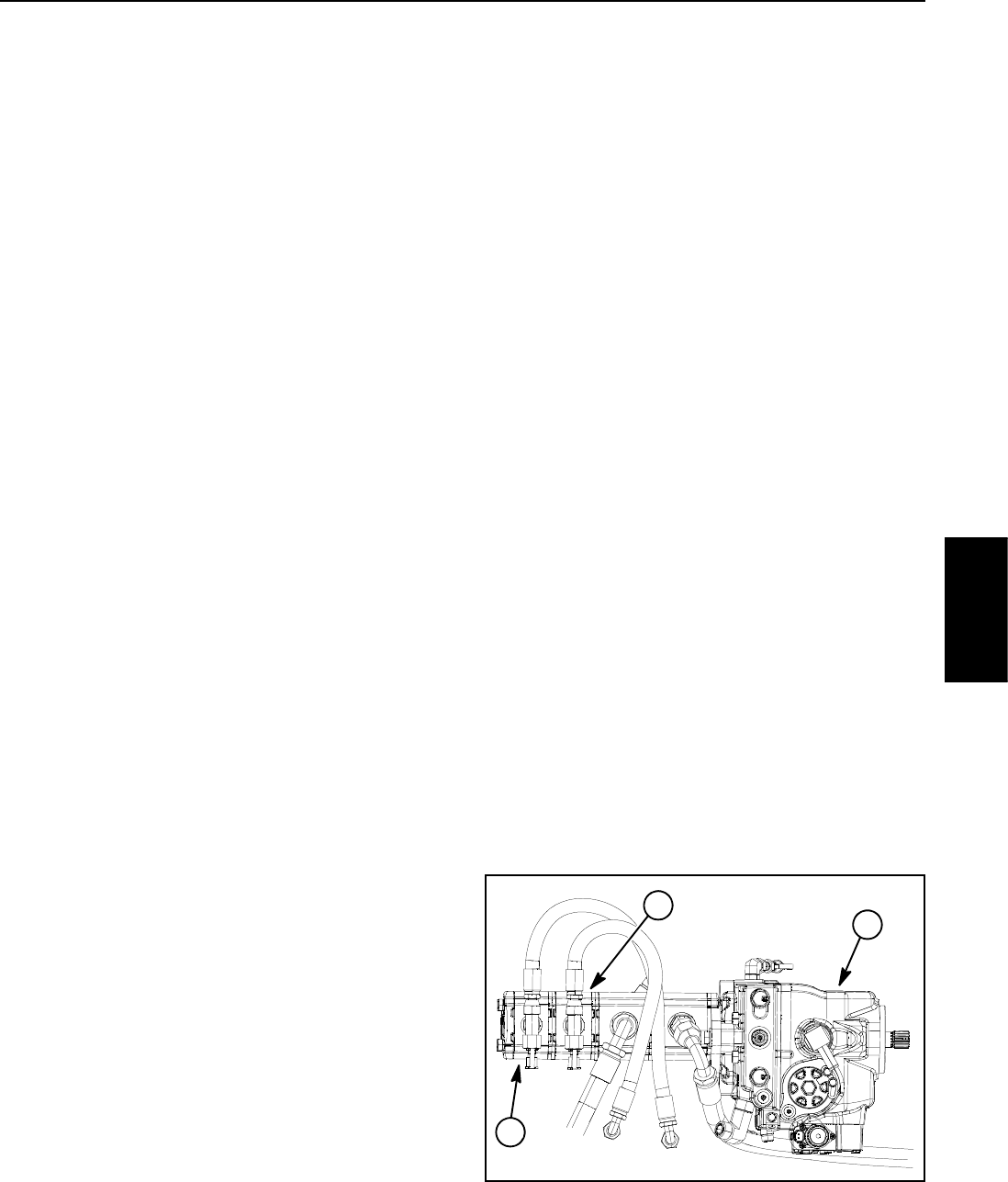
A four section gear pump is coupled to the piston (trac-
tion) pump (Fig. 14). The fourth gear pump section
(farthest from the piston pump) supplies hydraulic flow
to the steering circuit, the engine cooling fan circuit and
the traction charge circuit. The third gear pump section
supplies hydraulic flow to the engine cooling fan circuit,
the lift/lower circuit and the traction charge circuit.
So that there is sufficient oil flow for the engine cooling
fancircuit, oilflowfrom eitherorboth ofthethird orfourth
gear pump section is used to drive the hydraulic cooling
fan motor depending on what other machine functions
are being used (steering, lift/lower). If additional oil flow
is needed for cooling fan operation in extreme condi-
tions (e.g. high ambient temperatures, cutting very
heavy grass), the TEC controller can allow flow from the
twopumpsectionstobecombined.
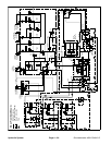
Oil flow from the third gear pump section is routed to the
combination manifold (port P3) where it is available
either for the lift/lower circuit or the engine cooling fan
circuit. Whenthe lift/lower circuitis not being used (alllift
switches in the neutral position), solenoid valve (S1) in
the combination manifold is not energized and gear
pump section oil flow is directed toward the engine cool-
ing fan motor.
Priority oil flow from the fourth gear pump section is
provided to the steering circuit. All excess flow from this
gear pump section is normally routed to the traction
charge circuit by energized solenoid valve (S11). This
valve is energized by the TEC controller as long as the
lift/lower function is not being used and the hydraulic oil
and engine coolant temperatures are within normal
ranges.If inputstothe TECcontroller suggest additional
oil flowis necessary forthe cooling fan (e.g.lift/lower cir-
cuit is engaged or engine coolant temperature is elev-
ated), solenoid valve (S11) will b e de--energized
allowing excess pump section oil flow to be directed to-
wardtheenginecoolingfanmotor.
Oil flow from the gear pump section(s) to the cooling fan
motor is controlled by the proportional relief valve (PRV)
in the combination manifold. This valve adjusts fan cir-
cuit pressure and flow based on a PWM (Pulse Width
Modulation) signal from the TEC controller. Thecontrol-
ler uses engine coolant and hydraulic oil temperatures
as inputs to determine the proper PWM signal for the
(PRV) valve. The fan circuit flow determines the speed
of the cooling fan motor and thus, the speed of the cool-
ing fan.
If the fan motor is stalled for any reason during machine
operation, the manifold proportional relief valve (PRV)
has a secondary function as a circuit relief to limit fan
motor pressure to 3250 PSI (224 bar).
When the engine is shut off, the over--running inertia
load of the engine cooling fan blades keeps driving the
fan motor and turns it into a pump. The check valve
(CV1) in the combination manifold will open to keep the
motor circuit full of oil so the fan motor will not cavitate.
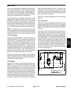
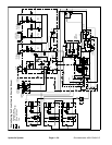
Forward Direction Fan Operation
Duringnormal, forwarddirection fanoperation,circuit oil
flow is sent through the de--energized solenoid valve
(S10) in the combination manifold to rotate the cooling
fan motor. Return flow from the motor re--enters the
manifold (port M2), through the de--energized solenoid
valve (S10), to the oil filter and then out of the manifold
(port CH2). After exiting the manifold, circuit oil is routed
to the traction charge circuit.
Reverse Direction Fan Operation
The TEC controller can reverse the cooling fan to clean
debris from the rear intake screen. If hydraulic oil and/or
engine coolant temperatures increase to an unsuitable
level, a high PWM signal is sent to the (PRV) valve to
slow the cooling fan and direct all pump oil flow to the
traction chargecircuit. The controller then energizes so-
lenoid valve (S10) in the combination manifold to re-
verse cooling fan motor oil flow so that the motor runs in
the reverse direction. A lower PWM signal is sent to the
(PRV) valve allowing oil flow to return to the fan motor
but in the reverse direction causing the motor and cool-
ing fan to run in reverse. The controller determines the
length of time that the fan should be run in reverse be-
fore fan rotation is returned to the forward direction.
NOTE: The operator can manually cause the cooling
fan to reverse by simultaneously pressing the right and
left buttons on the InfoCenter display.
1. Piston (traction) pump
2. 4
th
gear pump section
3. 3
rd
gear pump section
Figure 14
2
3
1
Hydraulic
System