


Groundsmaster 4000--D/4010--D Page 5 -- 57 Electrical System
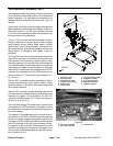
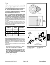
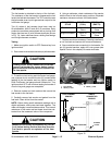
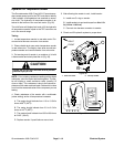
Fuel Sender
The fuel sender is attached to the top of the fuel tank.
The resistance of the fuel sender increases as the fuel
levelin thefuel tankdecreases. TheTEC controller uses
the fuel sender as an input to generate an output for the
InfoCenter fuel gauge.
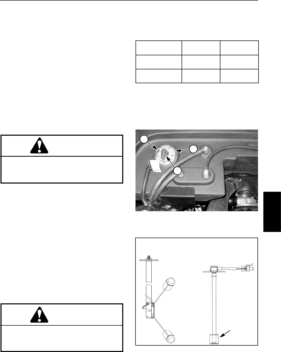
Two (2) styles of fuel senders have been used on
Groundsmaster 4000 --D and 4010--D machines. Early
production machines are equipped with a pivoting float
design that has two (2) wire harness terminals (shown
in Fig. 74). Later machines have a sliding float design
and a single harness connector.
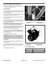
Testing
1. Make sure ignition s witch is OFF. Remove key from
ignition switch.
2. Disconnectwire harnessconnector(s)at fuelsender.
CAUTION
If testing circuit wiring, make sure wire connec-
tions at fuel sender are secure before t urning
ignition switchto RUNto preventan explosion or
fire from sparks.
3. To test the circuit wiring and InfoCenter fuel gauge,
use a jumper wire to connect the two (2) harness wires
leading to the fuel sender and turn ignition switch to
RUN. InfoCenter fuel gauge should indicate full. Turn
ignition switch OFF and continue testing fuel sender if
circuit wiring and gauge are acceptable.
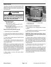
4. Remove screws and lock washers that secure the
fuel sender to the fuel tank.
5. Carefully remove fuel sender and gasket from the
fuel tank. Clean all fuel from the sender.
NOTE: Before taking small resistance readings with a
digital multimeter, short meter test leads together. The
meter will display a small resistance value. This internal
resistance of the meter and test leads should be sub-
tracted from the measured value of the component.
CAUTION
Make sure fuel sender is completely dry (no fuel
on it) before testing. Perform test away from the
fuel tank to prevent an explosion or fire from
sparks.
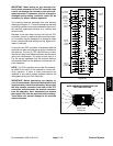
6. Using a multimeter, check resistance of the sender
with the float in the full and empty positions. Expected
resistance values are shown in the table below.
CONNECTOR
STYLE
RESISTANCE
(FULL)
RESISTANCE
(EMPTY)
Two Terminals 27.5 to 39.5
Ohms
240to260
Ohms
Single Connector 28 to 33
Ohms
240to250
Ohms
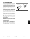
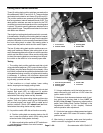
7. Replace senderasnecessary.Carefully installsend-
er into fuel tank and secure with removed fasteners.
8. Secure wire harness connector(s) to fuel sender. On
two (2) terminal senders, apply skin--over grease (see
Special Tools in this chapter) to sender terminals.
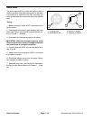
1. Fuel sender
2. White (+) lead
3. Black (--) lead
Figure 74
1
2
3
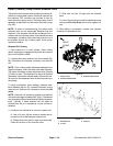
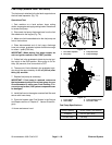
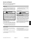
Figure 75
FULL POSITION
EMPTY POSITION
TWO TERMINAL SINGLE
CONNECTOR
SLIDING
FLOAT
SENDER
SENDER
Electrical
System