


Groundsmaster 4000--D/4010--DHydraulic System Page 4 -- 88
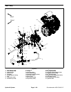
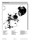
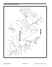
Installation (Fig. 61)
1. If fittings were removed from piston pump, lubricate
and place new O--rings onto fittings. Install fittings into
pump openings using marks made during the removal
process to properly orientate fittings. Tighten fittings
(see Hydraulic Fitting Installation in the General Infor-
mation section of this chapter).
IMPORTANT: To prevent spring coupler damage,
make sure that piston pump is properly supported
anddoesnot putsideload intocoupler duringpump
installation.
2. Carefully raise piston pump into the machine, align
pump input shaft to spring coupler on engine and posi-
tion it to the engine flywheel plate. Support pump to pre-
vent it from producing any side load into coupler and
also to align pilot diameter of pump to flywheel plate
bore.
3. While maintaining pump alignment with spring cou-
pler and flywheel plate, install two (2) cap screws and
washers to secure piston pump to engine.
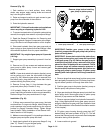
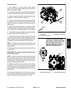
IMPORTANT: A case drain exists in the piston (trac-
tion) pump and a suction port is near the input shaft
of the gear pump (Fig. 63). Before the gear pump is
installed to the piston pump, make sure that plugs
placed in either of these ports are removed. Failure
to remove plugs will cause excessive pressure in
the piston pumpand damage seals. Also, before se-
curing gear pump to piston pump, fill piston pump
housing with clean hydraulic oil through case drain
hole.
4. Remove plugs that were placed in piston pump case
drainand gear pumps uction port. Fillpistonpump hous-
ing with new hydraulic oil through case drain hole.
5. Install gear pump to piston pump (see Gear Pump in
this section).
6. Using labels placed during pump removal, connect
wire harness connectors to the two (2) solenoid coils on
left side of piston pump.
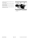
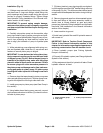
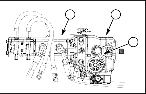
7. Fill piston (traction) pump housing with new hydraul-
icoil through thecasedrain (90
o
barbedfitting)at thetop
of thepump (Fig.64). This willensure that internalpump
components have adequate lubrication during initial op-
eration.
8. Remove plugs and caps from disconnected hydrau-
lic lines and fittings of the pump assembly. Install hy-
draulic lines to correct location on gear and piston
pumps (see Hydraulic Fitting Installation and Hydraulic
Hose and Tube Installation in the General Information
section of this chapter).
9. Lower machine to ground.
10.Install new hydraulic filter and fill hydraulic reservoir
with correct oil.
IMPORTANT: Refer to Traction Circuit Component
Failure in the General Information section of this
chapter forinformation regarding theimportance of
removing contamination from the traction circuit.
11.Prime hydraulic pumps (see Priming Hydraulic
Pumps in this section).
12.Properly fill hydraulic system (see Charge Hydraulic
System in this section).
13.Stop e ngine and check for hydraulic oil leaks. Check
hydraulic reservoir oil level.
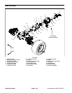
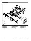
1. Piston (traction) pump
2. Gear pump
3. Piston pump case drain
Figure 64
2
3
1