


Groundsmaster 4000--D/4010--D Cutting DecksPage 8 -- 13
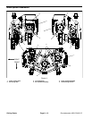
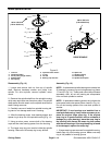
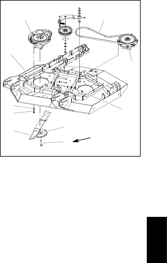
Removal (Figs. 11 and 12)
1. Park machine on a level surface, lower cutting
decks, stop engine, apply park ing brake and remove
key from the ignition switch.
2. Remove covers from cutting deck to allow access to
spindle a ssemblies.
3. If drive spindle assembly is to be serviced, remove
hydraulic motor fromcutting deck(seeCuttingDeck Mo-
torRemovalin theServiceandRepairsSectionof Chap-
ter 4 -- Hydraulic Systems). Position motor away from
spindle.
4. Loosen idler assembly to release drive belt tension
(see Idler Assembly Removal in this section). Remove
drive belt from spindle assembly that is to be serviced.
5. Start the engine and raise the cutting deck. Stop en-
gine and remove key from the ignition switch. Latch or
block up the cutting deck so it cannot fall accidentally.
6. Remove cutting blade, anti--scalp cup and blade bolt
from spindle assembly that is to be serviced.
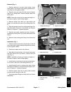
7. Remove spindle assembly from deck.
A. For driven spindle assemblies, remove eight (8)
flange nuts t hat secure spindle assembly to deck.
B. Fordrive spindleassemblies, removefour(4) cap
screws with washers that secure spindle assembly
and hydraulic motor mount to deck. Remove motor
mount. Then, remove four(4) flangenuts thatsecure
spindle assembly to deck.
C. Lift spindle assembly from deck.
8. If necessary, press screws from spindle housing.
Installation (Figs. 11 and 12)
1. If screws were removed from spindle housing, press
new screws into housing. Make sure that screw head is
squarely seated against housing after installation.
2. Position spindle assembly on cutting deck noting ori-
entation of grease fitting (Fig. 11). Secure spindle as-
sembly to deck with removed fasteners.
3. Install cutting blade, anti--scalp cup and blade bolt to
spindle. Tighten blade bolt from 88 to 108 ft--lb (120 to
146 N--m).
4. Slowly rotate cutting blades to verify that blades do
not contact any deck components.
5. Install drive belt to spindle pulleys and idler pulley.
Adjustdrive belt tension (seeIdler Assembly Installation
in this section).
6. If drive spindle assembly was removed, install hy-
draulic motor to cutting deck (see Cutting Deck Motor
Installation in the Service and Repairs Section of Chap-
ter 4 -- Hydraulic Systems).
IMPORTANT: Pneumatic grease guns can produce
air pocketswhen filling large cavities and therefore,
are not recommended to be used for proper greas-
ing o f spindle housings.
7. Attach a hand pump grease gun to grease fitting on
spindle housing and fill housing cavity with grease until
grease starts to come out of lower seal.
8. Install covers to cutting deck.
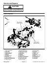
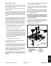
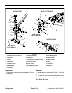
1. Deck (RH shown)
2. Driven spindle assembly
3. Drive spindle assembly
4. Flange nut
5. Drive belt
6. Washer
7. Cap screw
8. Blade
9. Anti--scalp cup
10. Blade bolt
Figure 12
1
2
6
4
5
3
7
8
9
10
88 to 108 ft--lb
(120 to 146 N--m)
Cutting
Decks