


Groundsmaster 4000--D/4010--D Hydraulic SystemPage 4 -- 135
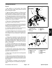
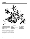
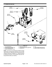
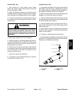
Removal (Fig. 101)
1. Read the General Precautions for Removing and
Installing Hydraulic System Components at the begin-
ning of the Service and Repairs section of this chapter.
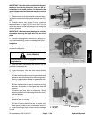
2. To prevent contamination of hydraulic system during
manifold removal, thoroughly clean exterior of PTO
manifold and fittings.
3. Disconnect wire harness connector from the propor-
tional relief valve coil on the PTO manifold.
4. Disconnect hydraulic lines from manifold and put
caps or plugs on open hydraulic lines and fittings. Label
disconnected hydraulic lines for proper installation.
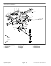
5. Remove PTO manifold from the frame using Figure
101 as a guide.
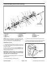
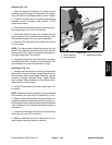
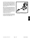
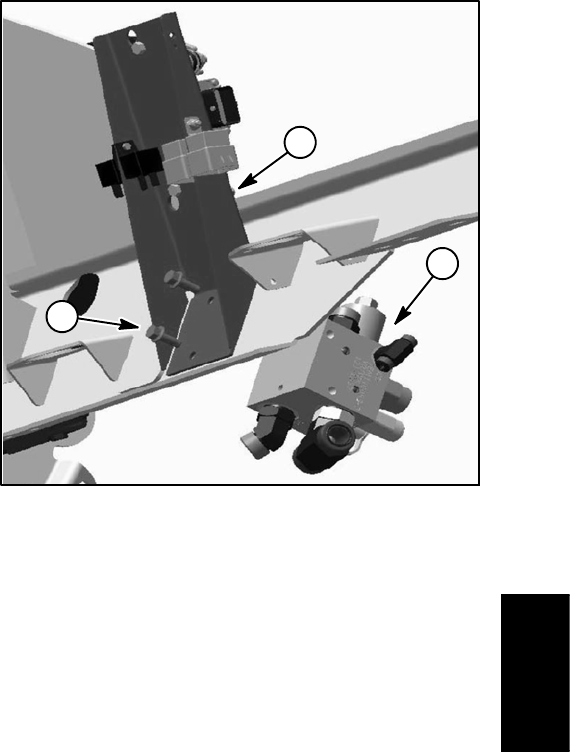
NOTE: The flange head screws that secure the right
side PTO manifold also secures the controller mount to
theframe (Fig.102). Support controllermount before re-
moving the right side PTO manifold.
6. If hydraulic fittings are to be removed from manifold,
mark fitting orientation to allow correct assembly. Re-
move fittings from manifold and discard O--rings.
Installation (Fig. 101)
1. If fittings were removed from manifold, lubricate and
place new O--rings onto fittings. Install fittings into man-
ifold openings using marks made during the removal
process to properly orientate fittings. Tighten fittings
(see Hydraulic Fitting Installation in the General Infor-
mation section of t his chapter).
2. Install PTO manifold to the frame using Figure 101
as a guide.
NOTE: Make sure that the controller mount is secured
when installing the right side PTO manifold (Fig. 102).
3. Remove caps and plugs from fittings and hoses. Us-
ing labelsplacedduring manifoldremoval, properly con-
necthydraulic linesto manifold (seeHydraulic Hoseand
Tube Installation in the General Information section of
this chapter).
4. Connect wire harness connector to the proportional
relief valve coil on the PTO manifold.
5. Make surehydraulic tank isfull. Addcorrect oil if nec-
essary before returning machine to service.
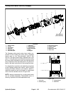
1. RH PTO manifold
2. Controller mount
3. Flange screw (2 used)
Figure 102
2
1
3
Hydraulic
System