


Groundsmaster 4000--D/4010--DPage 5 -- 34Electrical System
PTO Switch
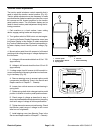
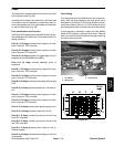
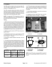
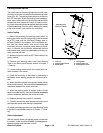
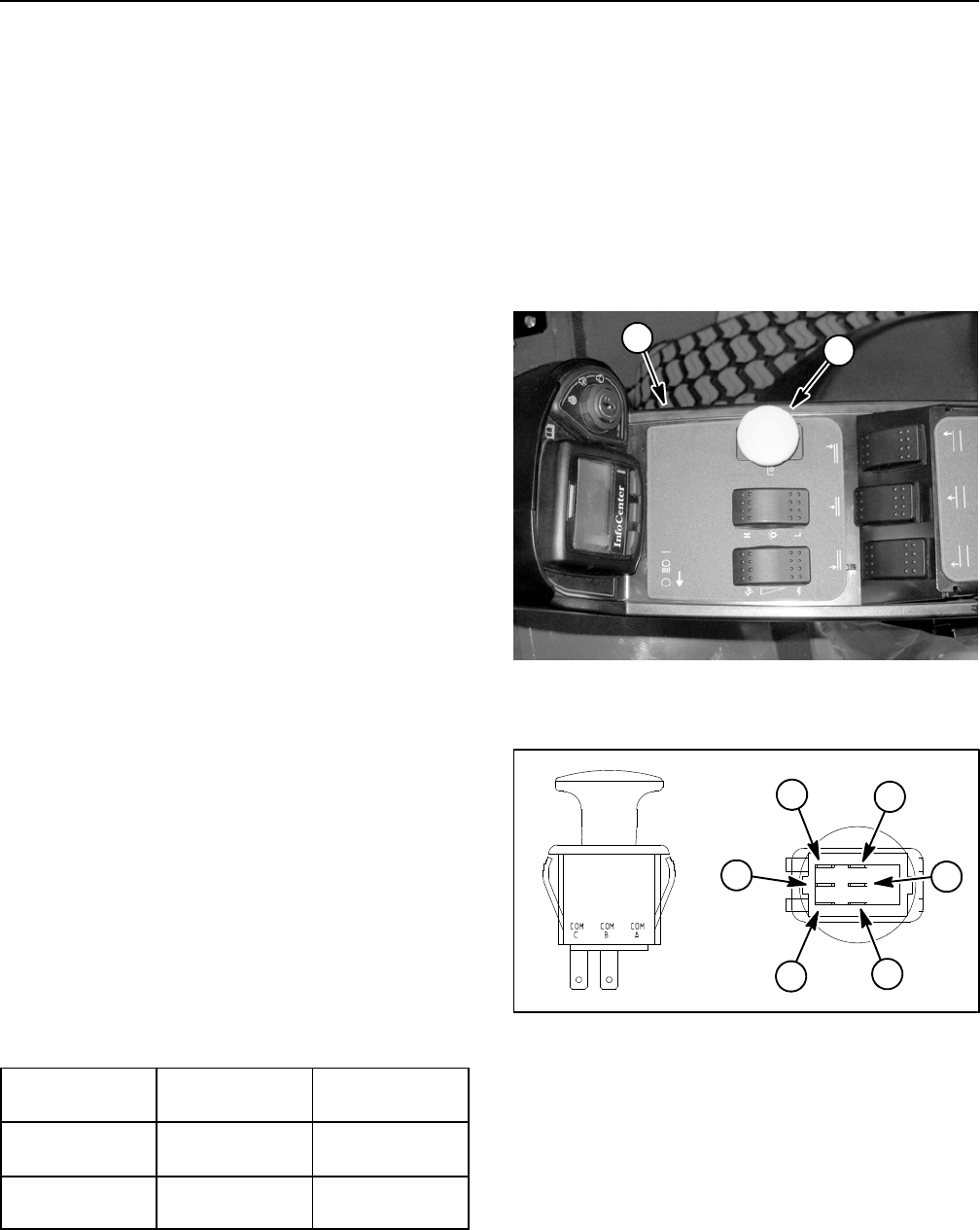
ThePTOswitchislocatedonthecontrolarm(Fig.35).
The PTO switch is pulled up to engage the PTO and
pushed in to disengage the PTO.
The TEC controller monitors the position of the PTO
switch (up or down). Using inputs from the PTO switch
and otherswitches inthe interlock system,the TECcon-
troller controls the energizing of the hydraulic solenoid
valves used to drive the cutting deck motors.
NOTE: To engage the PTO, the seat has to be occu-
pied,traction speedhas to be inLOW rangeand thecut-
ting decks have to be fully lowered.
Testing
1. Before disconnecting the PTO switch for testing, the
switch and its circuit wiring should be tested as a TEC
input with the InfoCenter Display (see InfoCenter Dis-
play in this chapter). If the InfoCenter verifies that the
PTO switch and circuit wiring are functioning correctly,
nofurtherswitch testingis necessary. If,however,theIn-
foCenter determines that the PTO switch and circuitwir-
ing are not functioning correctly, proceed with test.
2. Make sure ignition switch is OFF. Remove key from
ignition switch.
3. Disassemble control arm to gain access to PTO
switch (see Control Arm in the Service and Repairs sec-
tion of Chapter 7 -- Chassis).
4. Disconnect harness electrical connector from the
PTO switch.
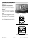
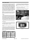
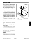
5. The switch terminals are marked as shown in Figure
36. The circuit logic of the PTO switch is shown in the
chartbelow.With theuse of amultimeter (ohmssetting),
the switch functions can be tested to determine whether
continuity exists between the various terminals for each
switch position. Verify continuity between switch termi-
nals. Replace PTO switch if testing identifies that switch
is faulty.
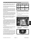
SWITCH
POSITION
CLOSED
CIRCUITS
OPEN
CIRCUITS
OFF (DOWN) COM B + NC B
COM C + NC C
COM B + NO B
COM C + NO C
ON (UP) COM B + NO B
COM C + NO C
COM B + NC B
COM C + NC C
6. If PTO switch tests correctly and circuit problem still
exists, check wire harness (see Electrical Schematics
and Wire Harness Drawings in Chapter 10 -- Foldout
Drawings).
7. After testing is completed, connect the wire harness
connector to the PTO switch.
8. Assemble control arm (see Control Arm in the Ser-
vice and Repairs section of Chapter 7 -- Chassis).
1. Control arm 2. PTO switch
Figure 35
2
1
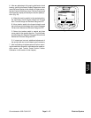
1. COM B terminal
2. NO B terminal
3. NC B terminal
4. COM C terminal
5. NO C terminal
6. NCCterminal
Figure 36
2
3
1
6
4
5
NOTE: Only PTO switch terminals COM C and NO C
are used on Groundsmaster 4000--D and 4010--D ma-
chines.