


Groundsmaster 4000--D/4010--D Hydraulic SystemPage 4 -- 17
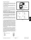
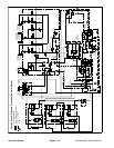
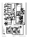
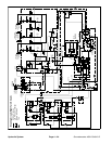
Lower Cutting Deck Circuit
A four section gear pump is coupled to the piston (trac-
tion) pump. The third gear pump section supplies hy-
draulic flowto thelift/lower circuit,the engine coolingfan
circuit and the traction charge circuit.
Each of the cutting decks (center, right and left) can be
loweredindependently withthe useof three (3)switches
on the armrest console. Pressing the front of a lift switch
providesan inputf or theTEC controllerto lower acutting
deck. The controller provides electrical outputs to sole-
noids in the combination manifold to allow appropriate
manifold valve shift that causes a cutting deck to lower.
A relief valve (RV2) located in the combination manifold
limits lift/lower circuit pressure to 1600 PSI (110 bar). An
adjustablepressurerelieving valve(PR) inthe combina-
tionmanifold maintainsback pressure (counterbalance)
on the deck lift cylinders to allow some of the cutting
deck weight to be transferred to the traction unit to im-
prove traction.
When the lift/lower circuit is not being used (all lift
switchesin the neutralposition),solenoid valveS1 inthe
combination manifold is not energized and gear pump
section oil flow is directed toward the engine cooling fan
motor.
NOTE: To lower a cutting deck, the operator must be in
the operator seat and the traction speed must be in the
LOW speed (mow) position.
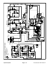
Lower Center Cutting Deck
To lower the center cutting deck, the front of the center
console lift switch is depressed. The switch signal is an
input to the TEC controller which provides an electrical
output to solenoid valve S6 in the combination manifold.
The energized solenoid valve shifts to allow a passage
for oilflowf rom thebarrel endof thecenter decklift cylin-
ders. The weight of the cutting deck causes the center
deck lift cylinders to retract and lower the center cutting
deck. Check orificeOR5( .070) underthe manifoldfitting
in port C2 controls the lowering speed of the cutting
deck. Oil fromthe retractingcylinders isdirected topres-
sure reducing valve (PR). As return oil pressure in-
creases, the PR valve will shift to direct circuit oil to the
oil filter and then to the traction charge circuit.
Lower Right Cutting Deck
Tolowertherightwingdeck,thefrontoftherightconsole
lift switch is pushed as an input to the TEC controller.
The controller provides an electrical output to solenoid
valves S1, S8 and S9 in the combination manifold. The
energized solenoid valves shift to allow a passage for
circuit oil flow to the rod end of the right deck lift cylinder.
Shifted S1 allows gear pump section oil flow to be avail-
able for the lift/lower circ uits. Shifted S8 allows an oil
path to the rod end of the right lift cylinder to retract the
lift cylinder and lower the right cutting deck. Check ori-
fice OR7 (.070) controls the lowering speed of the cut-
ting deck. Oil from the retracting cylinder is directed
through energized S9, de--e nergized S7 and then to
pressure reducing valve (PR). As return oil pressure in-
creases, the PR valve will shift to direct circuit oil to the
oil filter and then to the traction charge circuit.
Lower Left Cutting Deck
To lower the left wing deck, the front of the left console
lift switch is pushed as an input to the TEC controller.
The controller provides an electrical output to solenoid
valves S1, S3 and S4 in the combination manifold. The
energized solenoid valves shift to allow a passage for
circuit oil flowto the left deck lift cylinder rod end. Shifted
S1 allows gear pump section oil flow to be available for
the lift/lower circuits. ShiftedS3allowsanoilpathtothe
rod end of the left lift cylinder to retract the lift cylinder
and lower the left cutting deck. Check orifice OR3 (.070)
controls the lowering speed of the cutting deck. Oil from
the retracting cylinder is directed through energized S4,
de--energized S2 and then to pressure reducing valve
(PR). As return oil pressure increases, the PR valve will
shift todirect circuit oil tothe oil filterand then to thetrac-
tion charge circuit.
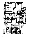
Cutting Deck Float
Cutting deck float allows the fully lowered cutting decks
to follow ground surface contours. Combination man-
ifoldsolenoid valvesS4 (leftdeck), S6( center deck) and
S9 (right deck) are energized when the decks are fully
lowered. These energized solenoids provide an oil pas-
sage to and from the lift cylinders to allow cylinder and
cutting deck movement while mowing. Counterbalance
pressure (PR) will affect deck float operation.
NOTE: If a deck is already fully lowered when the igni-
tion switch is moved from OFF to RUN, the deck will not
be in float until the appropriate deck lift/lower switch is
momentarily pressed to lower.
Hydraulic
System