


Groundsmaster 4000--D/4010--DPage 5 -- 12Electrical System
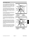
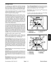
Diagnostics Screen
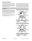
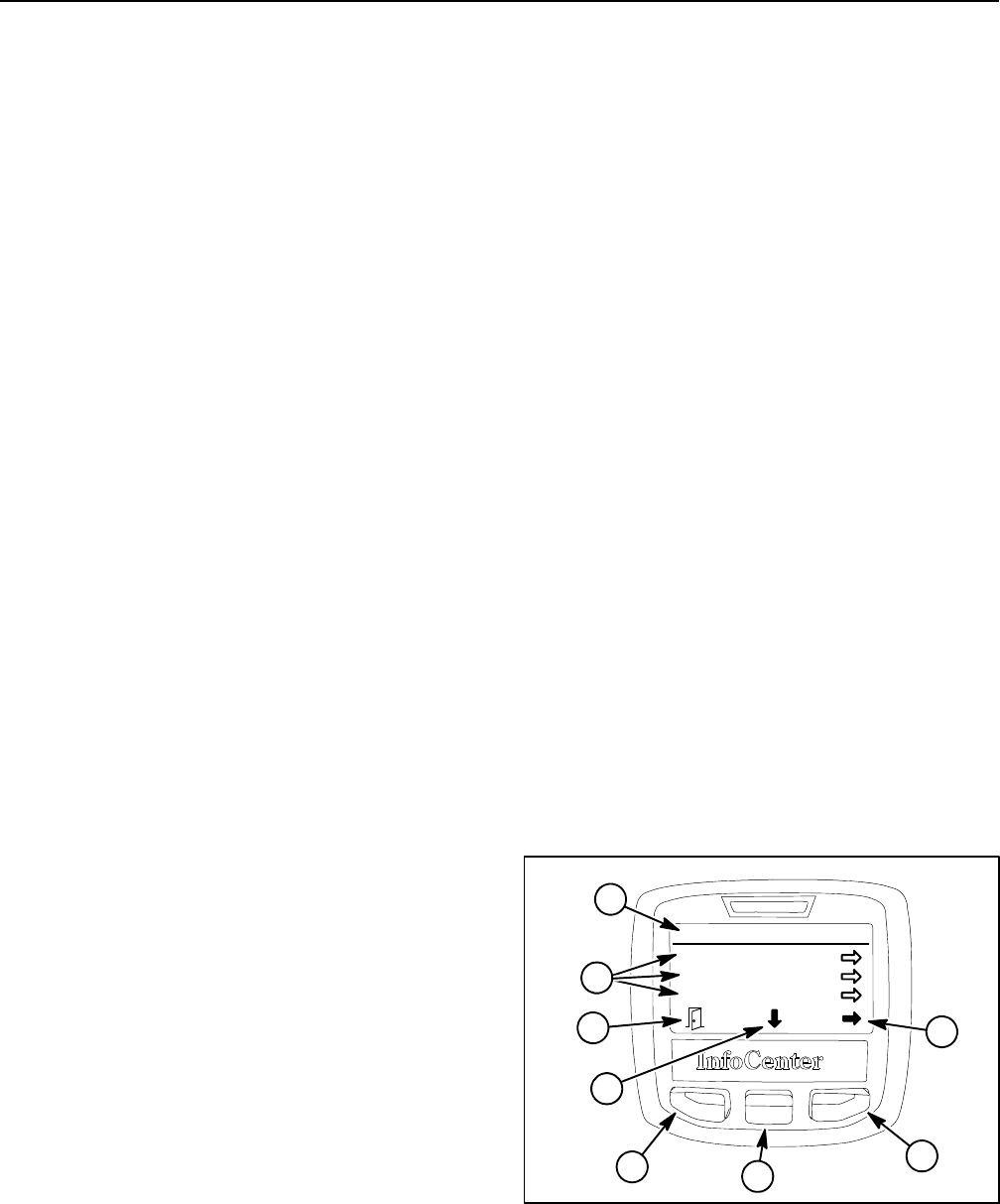
The diagnostics screen (Fig. 16) lists the various states
of machine electrical components. The diagnostics
screen should be used to check operation of machine
controls and to verify that switches and circuit wiring are
functioning correctly.
For each of the diagnostics screen items, inputs, qualifi-
ers and outputs are identified. The diagnostics screen
includes the following:
D Left Deck identifies machine requirements to allow
the left deck to raise and lower. Inputs indicate the state
of theleft decklift/lower switchand whether themachine
is in LOW range speed. Qualifiers include the LOW
range speed, seat switch and parking brake position.
Identified outputs consist of master, lower, raise and
float solenoids.
D Center Deck identifies machine requirements to al-
low the center deck to raise and lower. Inputs indicate
the state of the center deck lift/lower switch. Qualifiers
include the LOW range speed, seat switch and parking
brake position. Identified outputs consist of master,
raise and float solenoids.
D RightDeck identifiesmachine requirements to allow
therightdecktoraiseandlower.Inputsindicatethestate
of the right deck lift/lower switch. Qualifiers include the
LOW range speed, seat switch and parking brake posi-
tion. Identified outputs consist of master, lower, raise
and float solenoids.
D TractionPedal identifiesposition ofthetraction ped-
al. Inputs indicate the state of the traction pedal position
sensor.Outputs indicate whether the traction circuit is in
forward, neutral or reverse.
D Traction identifies machine requirements to allow
the traction system to be engaged. Inputs indicate the
state of the traction pedal. Qualifiers include the seat
switch and parking brake position. Outputs indicate
whether the piston (traction) pump is engaged in for-
ward or reverse.
D Hi/Low Range identifies machine requirements to
allowHIor LOWspeed range tobeengaged.Inputs indi-
cate the state of the hi/low s witch. Qualifiers identify the
position of the PTO switch and the cutting decks (raised
or lowered). Outputs indicate whether HI range is en-
gaged (solenoid S12 is energized).
D PTO identifies machine requirements to allow the
PTO tobe engaged. Inputsindicate the state of thePTO
switch. Qualifiers identify whether LOW speed range is
selected, if the seat is occupied and if the cutting decks
are lowered. Outputs indicate which cutting decks are
engaged.
D Engine Run identifies whether necessary TEC out-
puts exists to allow the engine to run. Inputs indicate the
state of the ignition switch. Qualifiers identify whether
the PTO isoff, ifthe traction pedalis in neutral, ifthe seat
is occupied (or parking brake is applied) and if all deck
lift switches a re not activated. O utputs indicate that re-
quirements have been met to allow engine to run or
start. NOTE: The components for engine operation (i.e.
glow plugs, starter) arecontrolled by the Yanmar engine
electronic control unit.
D Cruise Control identifies machine requirements to
allow the cruise control to be engaged. Inputs indicate
the state of the cruise control switch and service brakes.
Qualifiers identify whether the seat is occupied, if the
parking or service brakes are applied and if the traction
pedal is not in neutral. Outputs indicate that the cruise
function is engaged.
D Light Kit identifies machine requirements to allow
machine lights (ifequipped) tobe energized. Inputsindi-
cate the state of the light switches. Outputs indicate that
the lights are energized.
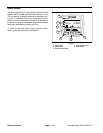
To return to the main menu screen from the diagnostics
screen, press the back button ( left button).
1. Diagnostics menu
2. Diagnostics items
3. Move to menu items
4. Choose menu item
5. Back button
Figure 16
Diagnostics
Left Deck
Center Deck
Right Deck
1
5
3
4
5
2
3
4