


Groundsmaster 4000--D/4010--D Hydraulic SystemPage 4 -- 69
Procedure for Gear Pump Flow
Test
CAUTION
Prevent personal injury and/or damage to equip-
ment. Read all WARNINGS, CAUTIONS and Pre-
cautions for Hydraulic Testing at the beginning
of this section.
1. Park machine on a level surface with the cutting
decks lowered and off. Make sure hydraulic oil is at nor-
mal operating temperature, engine isoff and theparking
brake is applied.
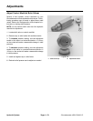
2. Raise and support operator seat to gain access to
gear pump.
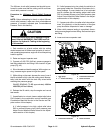
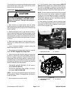
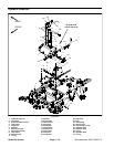
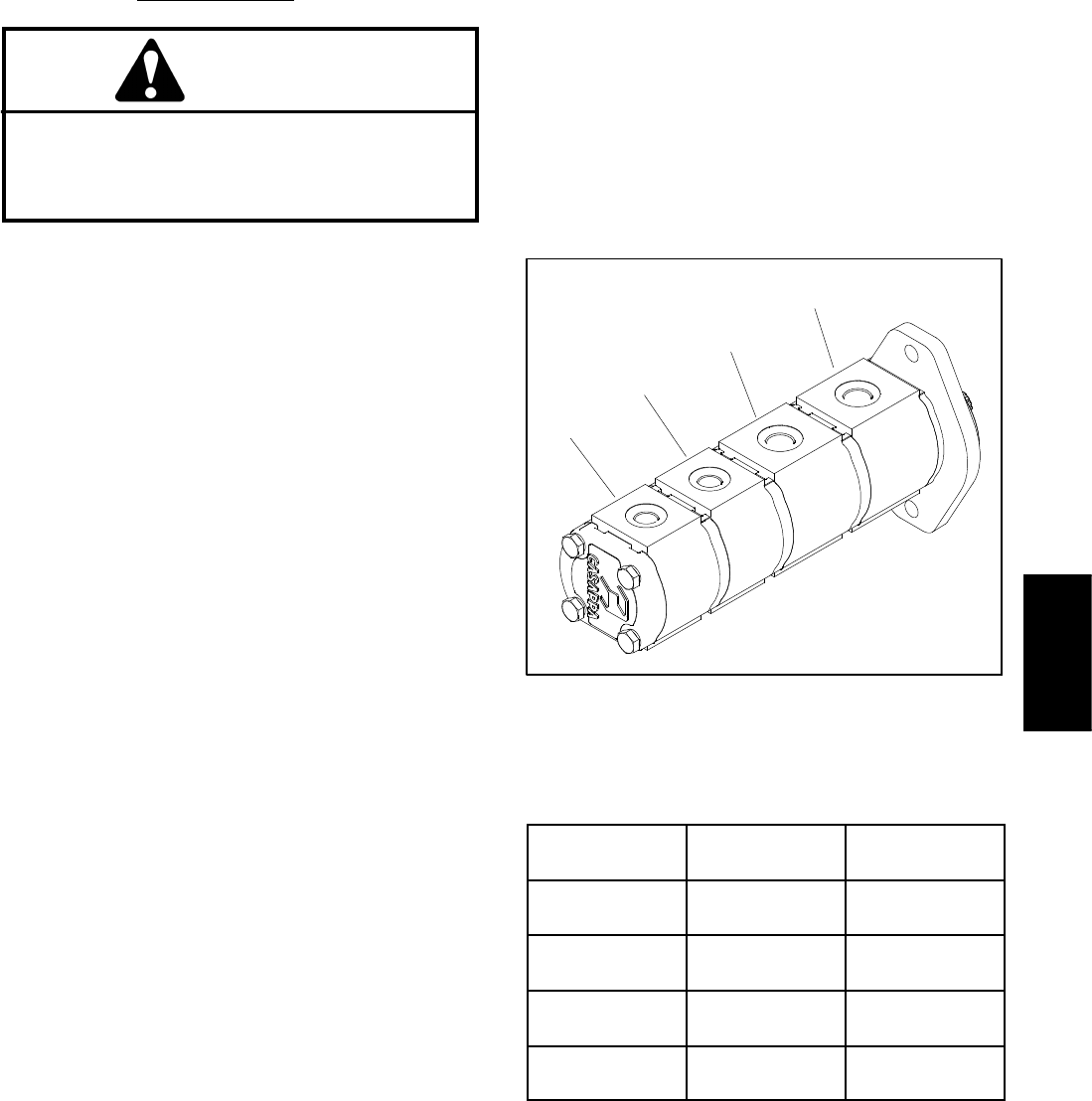
3. Determine which gear pump section is to be tested.
Disconnect hydraulic hosefrom fitting ingear pump sec-
tion that is to be tested (Fig. 47).
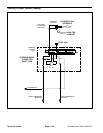
4. Install tester (flow and pressure) in series with the
disconnected hose and hydraulic fitting in gear pump
section.
5. Make sure the flow control valve on tester is fully
open.
6. Start engine and increase engine speed to high idle
speed. Do not engage the cutting decks.
IMPORTANT: Do not fully restrict oil flow through
tester. In this test, the flow tester is positioned be-
fore the relief valve. Pump damage can occur if the
oil f low is f ully restricted.
7. Watch pressure gauge carefully while slowly closing
the flowcontrol valveuntil 1000PSI (69bar) isobtained.
Verify with the InfoCenter display that the engine is still
running at the correct high idle speed.
NOTE: If engine speed drops during testing,pump flow
will decrease and flow test results will be inaccurate.
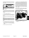
8. Normalflow indication forthe four(4)gearpumpsec-
tionsislistedinFigure48.
9. Shut off engine and record test results.
10.If apressureof 1000PSI(69 bar) cannotbe obtained
or flow was less than t he minimum flow listed in Figure
48, check for r estriction in the pump intake line. If line is
not restricted, consider that the tested gear pump sec-
tion is worn or damaged.
11.After testing is completed, disconnect flow tester
fromhydraulichose andfittingin gearpumpsection. Re-
connect hose to the pump fitting.
12.Lower and secure operator seat.
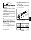
1. Front pump section (LH and RH PTO)
2. 2
nd
pump section (front PTO)
3. 3
rd
pump section (cooling fan, lift/lower and charge)
4. 4
th
pump section (steering, ch arge and cooling fan)
Figure 47
2
3
1
4
PUMP
SECTION
NORMAL
FLOW
MINIMUM
FLOW
FRONT
SECTION
14 GPM
(53 LPM)
11 GPM
(41.6 LPM)
SECOND
SECTION
14 GPM
(53 LPM)
11 GPM
(41.6 LPM)
THIRD
SECTION
4.3 GPM
(16.3 LPM)
3.4 GPM
(12.8 LPM)
FOURTH
SECTION
3.2 GPM
(12.1 LPM)
2.5 GPM
(9.5 LPM)
Figure 48
Hydraulic
System