Groundsmaster 4000--D/4010--DHydraulic S ystem Page 4 -- 106
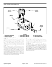
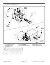
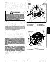
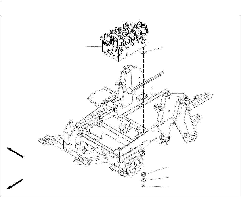
Combination Manifold
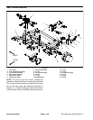
1. Combination manifold
2. Flange nut (3 used)
3. Flat washer (3 used)
4. Mount (3 used)
5. Spacer (3 used)
Figure 74
FRONT
RIGHT
2
3
1
5
4
NOTE: The ports on the combination manifold are
marked for easy identification of components. Example:
P3andP4arethegearpumpconnectionports,S1isthe
locationfor solenoidvalve S1andOR6 isthe locationfor
orifice OR6 (see Hydraulic Schematic in Chapter 10 --
FoldoutDrawings to identify thefunction ofthe hydraulic
lines and cartridge valves at each port).


