


Groundsmaster 4000--D/4010--DHydraulic S ystem Page 4 -- 100
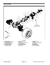
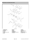
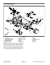
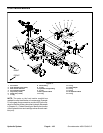
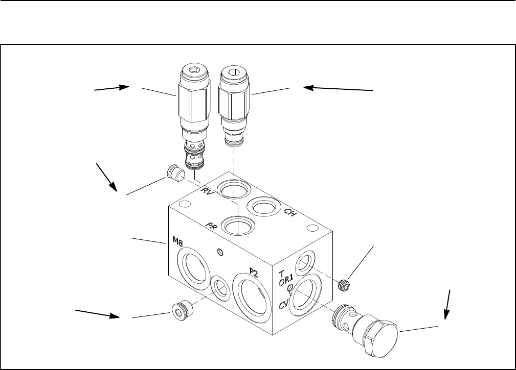
Rear Traction Manifold Service
1. Rear traction manifold body
2. Relief valve (port RV)
3. Pressure reducing valve (port PR)
4. #4 z ero leak plug with O--ring
5. #6 z ero leak plug with O--ring
6. Check valve (port CV)
7. Orifice (0.050) (port OR 1)
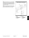
Figure 71
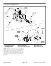
25 ft--lb
(34 N--m)
35 ft--lb
(47 N--m)
20 ft--lb
(27 N--m)
50 ft--lb
(67 N--m)
1
2
4
3
5
6
7
25 ft--lb
(34 N--m)
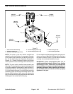
NOTE: The ports on the rear traction manifold are
marked for easy identification of components. Example:
P2 is a piston pump connection port and RV is the loca-
tion for the relief valve (see Hydraulic Schematic in
Chapter 10 -- Foldout Drawings to identify the function
of the hydraulic lines and cartridge valves at each port).
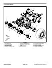
NOTE: The rear traction manifold uses several zero
leak plugs. These plugs have a tapered sealing surface
on the plug head that is designed to resist vibration in-
duced plug loosening. The zero leak plugs also have an
O--ring as a secondary seal. If zero leak plug removal is
necessary, lightly rap the plug head using a punch and
hammer before using an allen wrench to remove the
plug: the impactwill allow plug removal with less chance
of damage to the socket head of the plug.
For rear traction manifold cartridge valve service proce-
dures, see Control Manifold Cartridge Valve Service in
this section. Refer to Figure 71 for rear traction manifold
cartridge valve and plug installation torque.
IMPORTANT: A flow control orifice (item 7) is lo-
cated beneath the hydraulic fitting in rear traction
manifold port T/OR1. If the orifice i s removed from
this manifold port,make sureto labelits positionfor
assembly purposes. When installing the orifice in
the manifold, make sure that the orifice is properly
tightened in the port.