


Groundsmaster 4000--D/4010--D Page 7 -- 21 Chassis
Some service procedures (e.g. removing the hydraulic
reservoir)requirethe operatorplatform tobe raised. The
followingstepscanbeusedtoraisetheplatform.
Disassembly (Fig. 19)
1. Park machine on a level surface, lower cutting
decks, stop engine, apply park ing brake and remove
key from the ignition switch.
2. Disconnect negative battery cable from battery ter-
minal and then disconnect positive cable from battery
(see Battery Service in the Service and Repairs section
of Chapter 5 -- Electrical System).
3. Remove steering tower covers (see Steering Tower
in this section).
4. Disconnect machine wire harness connector from
position sensor on traction pedal assembly.
5. Remove fasteners that secure traction pedal as-
sembly to operator platform and then remove traction
pedal assembly from platform (Fig. 21).
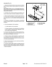
6. Disconnect bothbrake cables from brakepedals and
operator frame (Fig.22). Accessto brakecable jamnuts
canobtained byremoving adjustment coveron operator
platform (Fig. 23). Position brake cables away from op-
erator platform.
7. Disconnect all electrical wire harness connections
between operator platform componentsand mainframe
locations. As needed, label disconnected electrical con-
nections for proper installation.
8. On Groundsmaster 4010 machines:
A. Remove operator cab from machine.
B. Remove cable ties that secure operator cab
coolant andair conditioner hoses in enginecompart-
mentto allowthe operator platformto beraised.Note
location of cable ties for assembly purposes.
NOTE: If desired, operator seat can be removed from
operator platform t o reduce overall weight of operator
platform assembly (see Operator Seat in this section).
9. Remove four (4) cap screws, flat washers, plain
washers and lock nuts that secure operator platform to
machine frame.
IMPORTANT: Make sure to not damage the electric-
al wire harness or other components while raising
the operator platform.
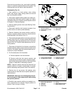
10.Carefully raise operator platform as needed to ac-
cess components to be serviced. Support platform to
prevent it from moving or shifting.
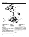
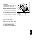
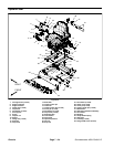
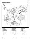
1. Operator platform
2. Flange screw (10 used)
3. Front cover
4. Clip (2 used)
5. Rear cover
Figure 20
2
3
1
5
4
2
2
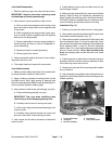
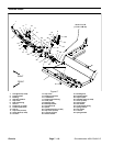
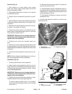
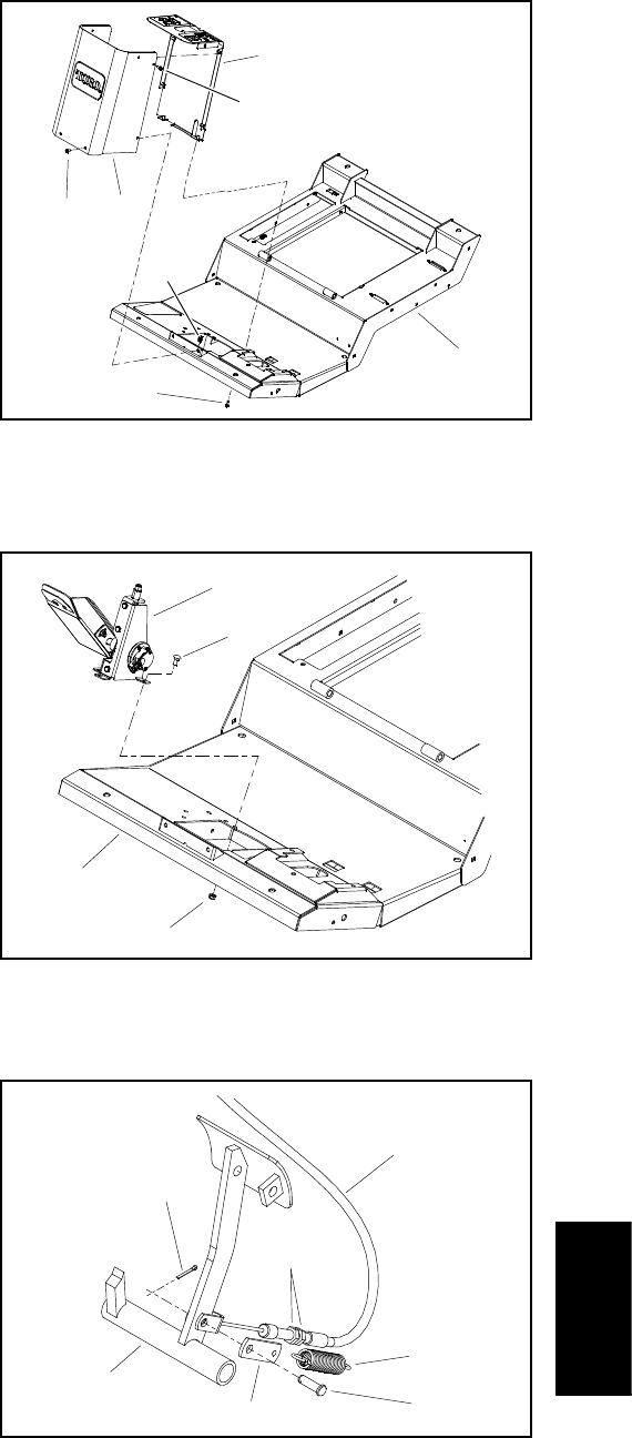
1. Traction pedal assembly
2. Carriage screw (4 used)
3. Flange nut (4 used)
4. Operator platform
Figure 21
3
1
4
2
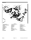
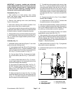
1. Brake pedal (RH s hown)
2. Cotter pin
3. Clevis pin
4. Brake strap
5. Spring
6. Brake cable (RH shown)
7. Brake cable jam nuts
Figure 22
2
1
3
4
5
6
7
Chassis