


Groundsmaster 4000--D/4010--D Cutting DecksPage 8 -- 9
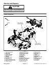
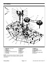
Removal (Fig. 5)
1. Position machine on a clean, level surface. Lower
cutting decks, stop engine, apply parking brake and re-
move key from the ignition switch.
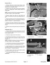
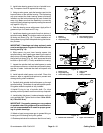
2. Remove hydraulic motor from cutting deck (see Cut-
ting Deck Motor Removal in the Service and Repairs
Section of Chapter 4 -- Hydraulic System).
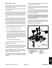
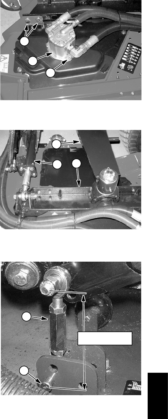
IMPORTANT: Donot changethe lengthof thedamp-
er link (Fig. 8).
3. Remove hairpin andclevis pin thatsecure the damp-
er link to the rear of the cutting deck (Fig. 8).
4. Remove eight (8) cap screws, lock washers and flat
washers thatsecure deck mount to cuttingdeck (Fig. 6).
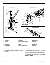
5. Raise lift arm enough to separate deck mount from
cutting deck (Fig. 7).
6. Slide the cutting deck away from the traction unit.
Installation (Fig. 5)
1. Position machine on a clean, level surface. Stop
engine, apply parking brake and remove key from the
ignition switch.
2. Position the side cutting deck to the lift arm and deck
mount.
3. Lower lift arm while aligning deck mount to cutting
deck.
4. Install deck mount to cutting deck with (8) cap
screws, lock washers and flat washers (Fig. 6). Tighten
fasteners.
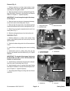
IMPORTANT: The length of the damper link should
be from 5.295” to 5.445” (134 to 138 mm) measured
between rod end centers.
5. Install clevis pin and hairpin that secure the damper
link to the rear of the cutting deck (Fig. 8).
6. Install hydraulic motor to cutting deck (see Cutting
Deck M otor Installation in the Service and Repairs Sec-
tion of Chapter 4 -- Hydraulic System).
7. Lubricate grease fittings on cutting deck and lift arm
assembly.
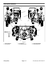
1. Flange head screw
2. Hydraulic motor
3. Deck mount screw
Figure 6
1
2
3
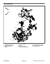
1. Lift arm (RH shown)
2. Rear arm assembly
3. Deck mount
Figure 7
1
2
3
1. Damper link 2. Clevis pin
Figure 8
1
2
5.295” to 5.445”
(134 to 138mm)
Cutting
Decks