


Groundsmaster 4000--D/4010--D Page 5 -- 35 Electrical System
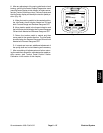
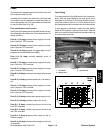
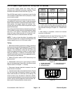
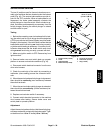
HI/LOW Speed, Engine Speed and Cutting Deck Lift Switches
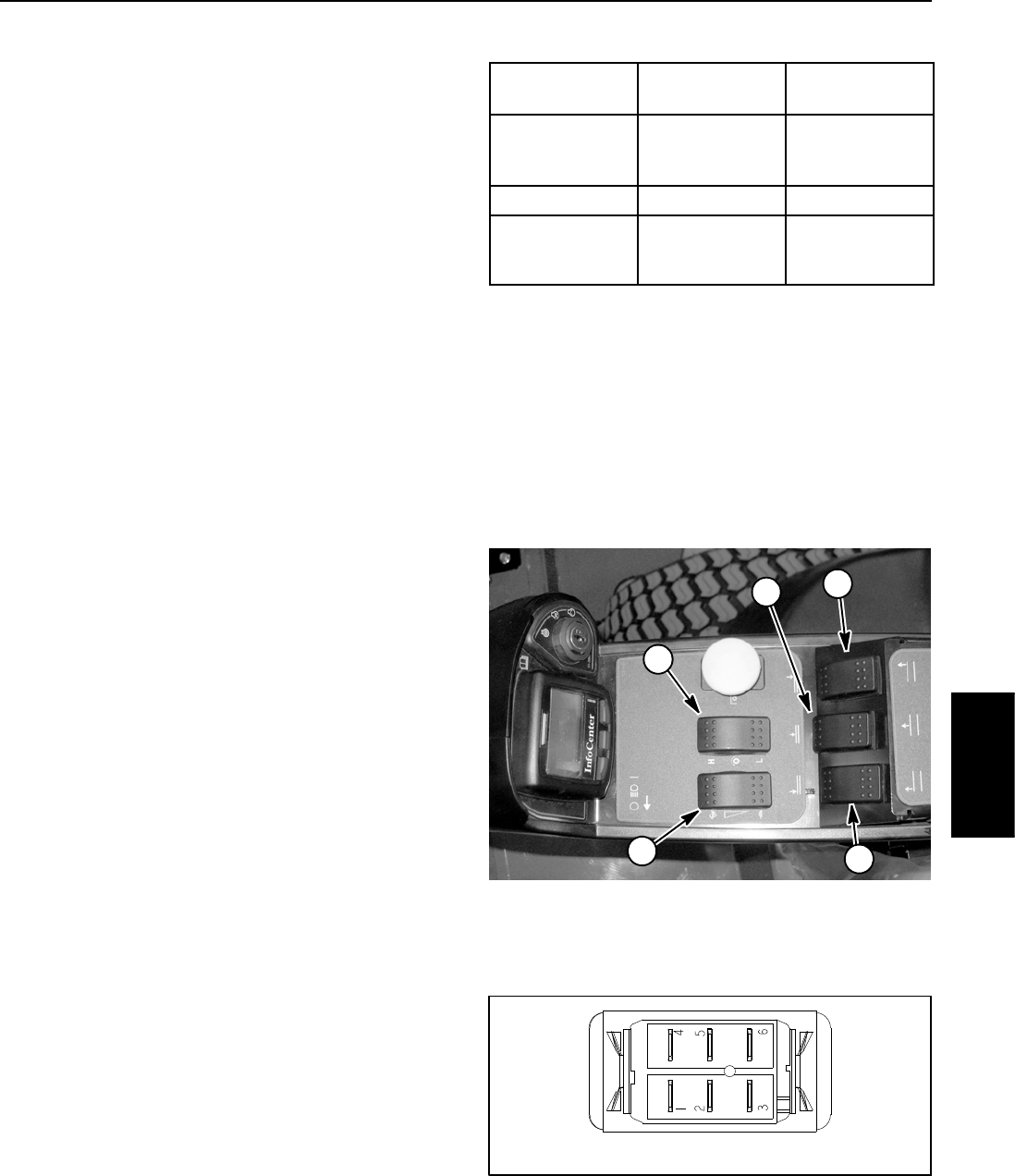
The HI/LOW, engine speed and cutting deck lift
switches are all identical momentary switches. These
switches are located on the control arm (Fig. 37).
The HI/LOW speed switch is used as an input for the
TEC controller to select either the HI (transport) or LOW
(mow) traction speed.
The engine speed switch is used as an input for the en-
gine electronic control unit to raise or lower the engine
speed.Whenthe switchisdepressed and heldin thefor-
ward position, the engine speed will increase. Con-
versely,when therear ofthe switchis depressed, engine
speed will decrease.
The cutting deck lift switches are used as inputs for the
TEC controller to raise or lower the cutting decks.When
the front of a lift switch is depressed, the controlled
decks will lower. When the rear of a lift switch is de-
pressed and held, the controlled decks will raise.
NOTE: To raise or lower the decks, the operator seat
has to be occupied. Also, to lower the cutting decks, the
traction speed has to be in LOW (mow) range.
Testing
1. Before disconnecting a switch for testing, the switch
andits circuitwiring should betested asa TECinputwith
the InfoCenter Display (see InfoCenter Display in this
chapter). If the InfoCenter verifies that the switch and
circuit wiring are functioning correctly, no further switch
testing is necessary. If, however, the InfoCenter deter-
mines that the switch andcircuit wiring are not function-
ing correctly, proceed with test.
2. Make sure ignition s witch is OFF. Remove key from
ignition switch.
3. Disassemble control arm to gain access to switch
that is to be tested (see Control Arm in the Service and
Repairs section of Chapter 7 -- Chassis).
4. Disconnect harness electrical connector from the
switch that is to be tested.
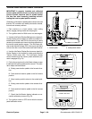
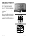
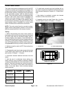
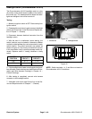
5. The switch terminals are marked as shown in Figure
38. The circuit logic of the switch is shown in the chart
below. With the use of a multimeter (ohms setting), the
switch functions may be tested to determine whether
continuity exists between the various terminals for each
position. Verify continuity between switch terminals.Re-
place switch if testing identifies a faulty switch.
SWITCH
POSITION
CLOSED
CIRCUITS
OPEN
CIRCUITS
FRONT OF
SWITCH
PRESSED
2+3
5+6
2+1
5+4
NEUTRAL NONE ALL
REAR OF
SWITCH
PRESSED
2+1
5+4
2+3
5+6
6. If switch tests correctly and circuit problem still ex-
ists, check wire harness (see Electrical Schematics and
Wire Harness Drawings in Chapter 10 -- Foldout Draw-
ings).
7. After testing is completed, connect wire harness
connector to the switch.
8. Assemble control arm (see Control Arm in the Ser-
vice and Repairs section of Chapter 7 -- Chassis).
1. HI/LOW speed switch
2. Engine speed switch
3. RH deck lift switch
4. Center deck lift switch
5. LH deck lift switch
Figure 37
2
1
3
5
4
Figure 38
BACK OF SWITCH
Electrical
System