


Groundsmaster 4010--D Operator CabPage 9 -- 11
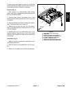
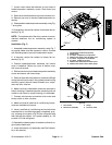
7. Loosen hose clamp that secures air duct hose to
heater/evaporator assembly covers. Slide hose from
covers.
8. Remove screwsthat secure topcover to bottomcov-
er. Remove top cover to access heater/evaporator as-
sembly.
9. Disassemble heater/evaporator assemblyusing Fig.
7 as a guide.
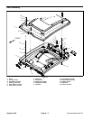
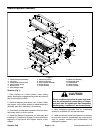
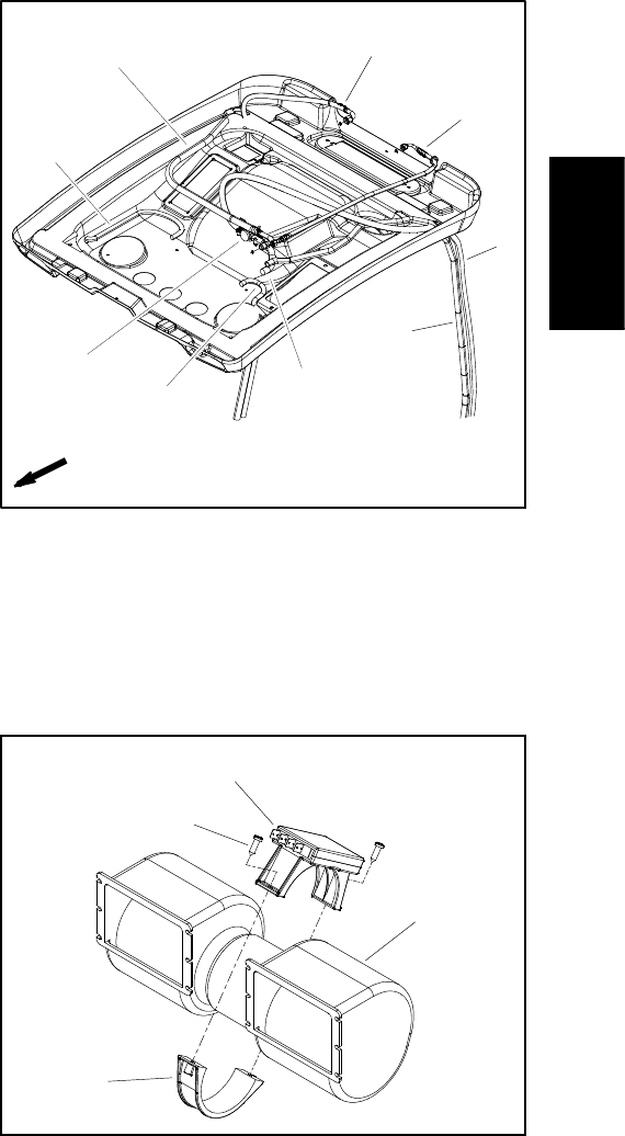
10.If necessary, remove fan resistor from blower fan as-
sembly (Fig. 9).
NOTE: Thereplacementof thedrier--receiver isrecom-
mended whenever the air conditioning system is
opened.
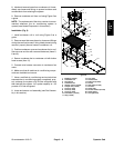
Installation (Fig. 7)
1. Assemble heater/evaporator assembly using F ig. 7
as a guide. Make sure that expansion valve is covered
with insulating tape to prevent condensation issues.
2. If removed, secure fan resistor to blower fan as-
sembly (Fig. 9).
3. Position heater/evaporator assembly into bottom
cover in headliner. Secure top cover to bottom cover
with removed screws.
4. Slide air duct hoseonto heater/evaporatorassembly
covers and secure with hose clamp.
5. Remove caps that were placed on hoses and fittings
during the removal process. Using labels placed during
removal, properly secure hoses to heater core, evapo-
rator and drier--receiver.
6. Make sure that condensation hoses are secured to
bottom housing of heater/evaporator assembly and are
routed to cab frame for proper draining of condensate.
7. Connect wire harness connectors to fan motor and
binary switch on drier--receiver.
8. Make sure that all machine air conditioning c ompo-
nents are installed and secure.
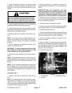
9. Have a certified air conditioning service technician
evacuate the air conditioning system completely, prop-
erly recharge the system with R134a refrigerant and
then leak test the system. A/C system capacity is 1.35
pounds of R134a refrigerant.
10.Operate the heater system to make sure that no en-
gine coolant leaks exist.
11.Lower and secure roof assembly (see Roof Assem-
bly in this section).
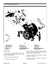
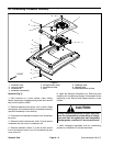
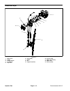
1. Condensation drain hose (2 used)
2. Heater valve
3. A/C hose: ev aporator to compressor
4. Heater hose: heater valve to heater core
5. A/C hose: compressor to condenser
6. A/C hose: condenser to drier
7. Heater hose: thermostat to heater valve
8. Heater hose: heater core to water pump
Figure 8
2
3
7
8
6
5
4
1
1
FRONT
1. Fan resistor
2. Blower fan assembly
3. Clamp
4. Screw (2 used)
Figure 9
2
1
3
4
Operator
Cab