


Groundsmaster 4000--D/4010--D Page 5 -- 55 Electrical System
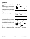
CAN--bus Termination Resistor
System communication between electrical components
on Groundsmaster 4000--D and 4010--D machines is
accomplished on a CAN--bus communication system.
Two (2) specially designed, twisted wires form the bus
for the network used on the machine. These wires pro-
vide the data pathways between machine components.
At the end of the twisted pair of bus wires near the In-
foCenter display is a 120 ohm termination resistor.
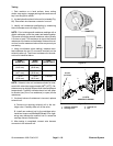
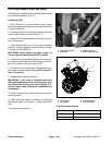
The CAN--bus termination resistor plugs into the plat-
formwire harnessin thecontrol arm.The resistorcan be
accessed by removing the cover plate on the right side
of the control arm. The wire harness connector has a
blue insert to identify the proper location for the termina-
tion resistor.
NOTE: The Groundsmaster 4000 --D and 4010--D en-
gineECU includes the secondCAN--b us system termin-
ation resistor. This resistor cannot be accessed for
testing.
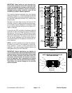
NOTE: Refer to the Electrical Schematics and Wire
Harness Drawings in Chapter 10 -- Foldout Drawings for
additional information on termination resistor location
and wire connections.
IMPORTANT: The termination resistor is required
for proper electrical system operation.
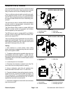
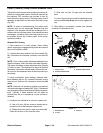
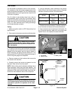
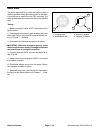
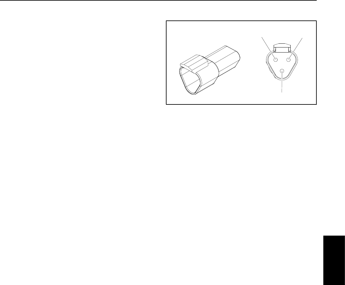
Termination Resistor Test
Theterminationresistor(Fig.73)canbetestedusinga
digital multimeter (ohms setting). There should be 120
ohms r esistance between terminals A and B of the ter-
mination resistor. Terminal C is not used on Ground-
smaster 4000--D and 4010--D machines.
Figure 73
Termination
A
B
C
Resistor
Electrical
System