


Groundsmaster 4000--D/4010--D Page 7 -- 29 Chassis
NOTE: Most of the seat suspension components can
be serviced with the seat suspension base mounted to
the frameplatform. If theair spring assembly (item 6)re-
quiresremoval, theseat suspensionbase willhaveto be
removed from the seat platform.
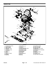
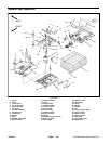
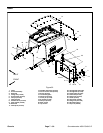
Disassembly (Fig. 29)
1. Remove operator seat from seat suspension (see
Operator Seat Removal in this section).
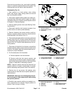
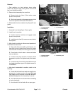
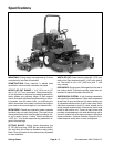
2. Disconnect seat suspension connector from ma-
chinewireharness(Fig.30).
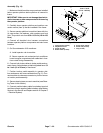
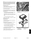
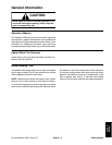
3. If the air spring assembly (item 6) or base plate (item
37) requires removal, remove seat suspension from
seat plate (Fig. 31):
A. Raise and support seat plate assembly. Support
seat suspension to prevent it from falling.
B. Remove four (4) cap screws, flat washers and
flange nuts that secure seat suspension to seat
plate.
C. Remove seat suspension from machine.
4. Remove seat suspension components as needed
using Figure 29 as a guide.
Assembly (Fig. 29)
1. Install all removed seat suspension components us-
ingFigure29asaguide.
2. If seat suspension was removed from seat plate, se-
cure suspension to seat plate (Fig. 31):
A. Position seat suspension onto seat plate.
B. Secure seatsuspension to seat platewith four(4)
cap screws, flat washers and flange nuts.
C. Lower and secure seat plate assembly.
3. Install operator seat to seat suspension (see Opera-
tor Seat Installation in this section).
4. Make sure that seat electrical connectors are con-
nected to machine wire harness (Fig. 30).
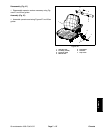
1. Operator seat
2. Seat switch connector
3. Suspension connector
Figure 30
1
2
3
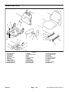
1. Seat suspension
2. Flat washer (4 used)
3. Cap screw (4 used)
4. Flange nut (4 used)
5. Seat plate
Figure 31
4
1
2
3
5
Chassis