


Groundsmaster 4000--D/4010--D Page 7 -- 5 Chassis
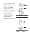
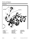
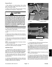
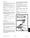
Removal (Fig. 3)
1. Park machine on a level surface, lower cutting
decks, stop engine, apply park ing brake and remove
key from the ignition switch.
2. Remove center cutting deck (see Center Cutting
Deck Removal in Chapter 8 -- Cutting Decks).
CAUTION
When changing attachments, tires or perform-
ing other service, use correct jacks and sup-
ports. Make sure machine is parked on a solid,
level surface such as a concrete floor. Prior to
raising machine, remove any attachments that
may interfere with the safe and proper raising of
themachine.Always chock orblock wheels.Use
jack stands to support t he raised machine. If the
machine is not properly supported by jack
stands, the machine may move or fall, which
may result in personal injury.
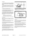
3. Chock rear wheels and jack up front of machine.
Support machine on jack stands.
4. Remove front wheel next to lift arm that is to be re-
moved.
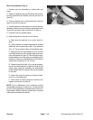
5. Remove cap screw, washers and lock nut that se-
cure liftcylinder pinto lift arm. Removepin and separate
lift cylinder and lift arm.
6. Remove lock nutthat secures lift arm pin. Support lift
arm and slide pin from frame and lift arm. Remove lift
armfromframe.
NOTE: The lift arm ball joint ( item 12) and jam nut (item
11) have left hand threads.
7. Remove height --of--cut chain, ball joint mount and
ball joint from removed lift arm as required.
Installation (Fig. 3)
1. Position lift arm to frame and insert lift arm pin. En-
gage roll pin into frame slots and install lock nut on pin.
Torque lock nut from 60 to 70 ft--lb (81 to 94 N--m).
Make sure that lift arm pivots freely after installation.
2. Align lift cylinder with lift arm. Slide pin through lift
arm and cylinder end. Secure pin with cap screw, wash-
ers and lock nut.
3. Install front wheel assembly and lower machine to
the ground. Make sure that wheel lug nuts are torqued
from 85 to 100 ft-- lb (115 to 135 N-- m).
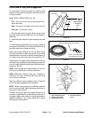
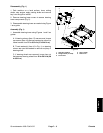
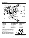
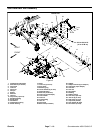
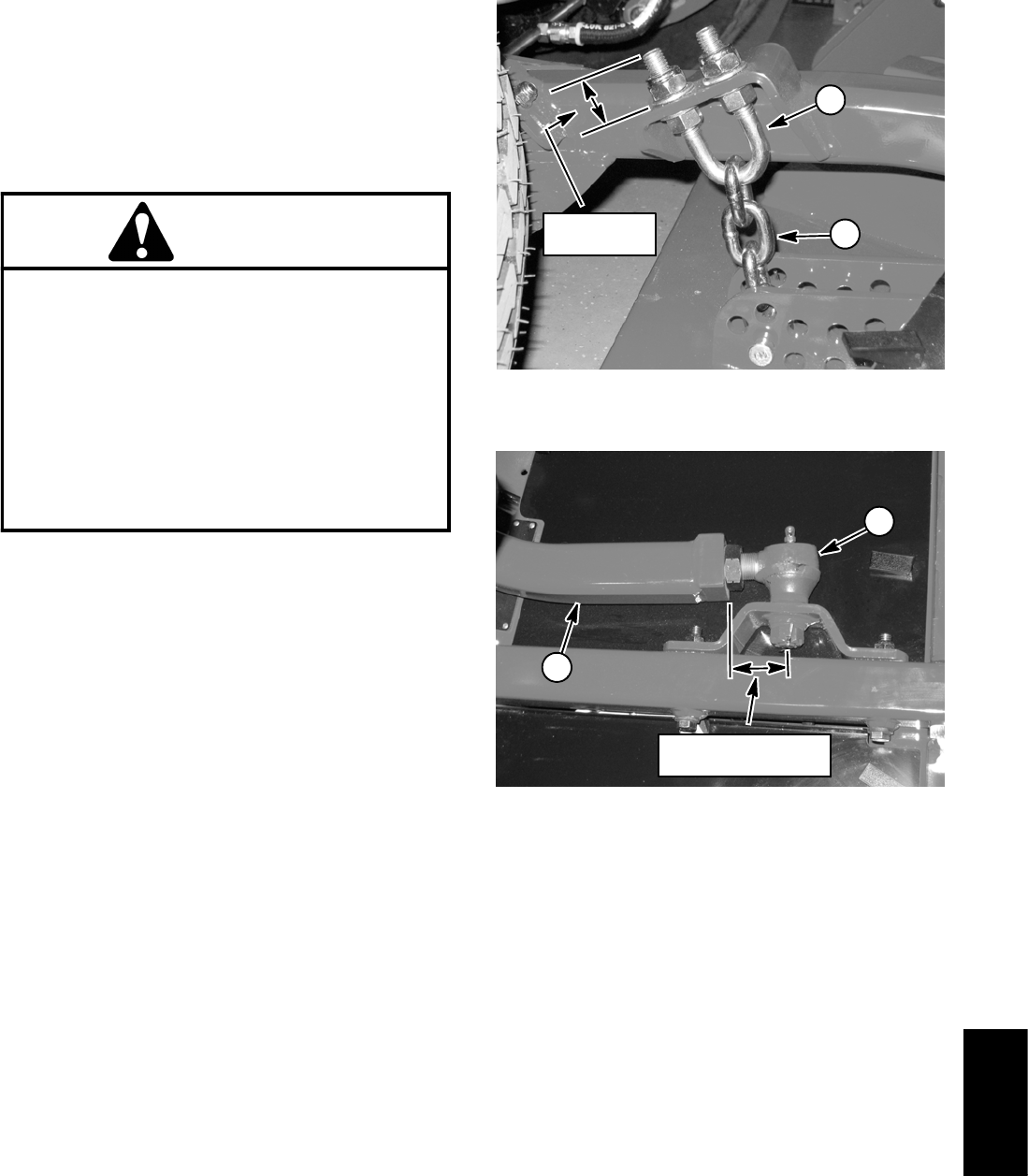
1. U--bolt 2. Height of cut chain
Figure 4
1.200”
(30.5 mm)
1
2
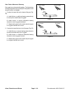
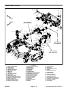
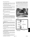
1. Lift arm 2. Ball joint
Figure 5
1
2
2.210” to 2.390”
(56.1 to 60.7 mm)
4. If sensing plate (item 32) was removed from lift arm,
secure plate fully forward in lift arm slot.
5. If height--of--cut chain u--bolt was removed from lift
arm, assemble u--bolt so that threaded portion extends
1.200” (30.5 mm) above lift arm mounting plate (Fig. 4).
This dimension is a starting point that might need addi-
tional adjustment for deck pitch correction (see step 12
below).
NOTE: The lift arm ball joint (item 12) and jam nut (item
11) have left hand threads.
6. If removed, install ball joint to lift arm. Distance from
endof liftarm tocenter ofballjoint shouldbe from2.210”
to 2.390” (56.1 to60.7 mm)(Fig. 5). Makesure that ball
joint is horizontal and that stud is centered in ball joint.
Install deck before torquing ball joint jam nut (item 24).
Chassis