


Groundsmaster 4000--D/4010--D Hydraulic SystemPage 4 -- 143
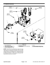
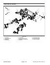
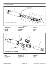
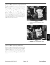
Disassembly (Figs. 108 and 109)
1. Removeoilfrom liftcylinderintoa drainpan byslowly
pumping the cylinder shaft. Plug both ports and clean
the outside of the cylinder.
IMPORTANT: Prevent damage when clamping the
cylinder in a vise; clamp on the clevis only.
2. Mount lift cylinder securely in a vise by clamping on
the clevis end of the barrel. Use of a vise with soft jaws
is recommended.
3. Loosen head from barrel:
A. Use a spanner wrench to rotate head clockwise
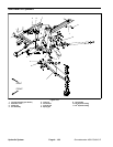
until the edge of the retaining ring (item 2 in Figure
108 or item 5 in Figure 109) appears in the barrel
opening.
B. Insert a screwdriver under the beveled edge of
the retaining ring to start the retaining ring through
the opening. Then, rotate the head counter--c lock-
wise to remove retaining ring from barrel and head.
4. Extract shaft with head and piston by carefully twist-
ing and pulling on the shaft.
IMPORTANT: Do not clamp vise jaws against the
shaft surface.
5. Mountshaft securelyin avise by clamping onthecle-
vis ofthe shaft.Use ofa visewith softjaws isrecommen-
ded.
6. Remove lock nut and piston from the shaft. Slide
headofftheshaft.
7. Remove and discard all seals and O--rings from the
piston and the head.
CAUTION
Use eye protection such as goggles when using
compressed air to dry cylinder components.
8. Wash cylinder parts in clean solvent. Dry parts with
compressed air. Do not wipe parts dry withpaper towels
or cloth. Lint in a hydraulic system will cause damage.
9. Carefully inspect internal surface of barrel for dam-
age (deep scratches, out--of--round, etc.). Inspect shaft
and piston for evidence of excessive scoring, pitting or
wear. Replace lift cylinder if internal components are
found to be worn or damaged.
Assembly (Figs. 108 and 109)
1. Make sure all cylinder components are clean before
assembly.
2. Coat new seal kit components with clean hydraulic
oil. Installnew lubricated sealsand O--ringsto the piston
and head.
IMPORTANT: Do not clamp vise jaws against the
shaft surface.
3. Mountshaft securelyin aviseby clampingon thecle-
vis of t he shaft. Use of a vise with soft jaws is recom-
mended.
A. Coat shaft with clean hydraulic oil.
B. Carefully slide head and then piston onto the
shaft. Secure piston to shaft with lock nut.
C. Torque lock nut to specification in Figure 108
(side deck cylinder) or Figure 109 (center deck cylin-
der).
4. Remove shaft assembly from vise.
IMPORTANT: Prevent damage when clamping the
hydraulic cylinder into a vise; clamp on the clevis
end o f the barrel ONLY.
5. Mount barrel securely in a vise by clamping on the
clevis end of the barrel. Use of a vise with soft jaws is
recommended.
IMPORTANT: When installing the head into the bar-
rel of the lift cylinder, pay careful attention to t he re -
tainingringslot inthebarrel to insurethat thepiston
and head seals do not lodge in the slot.
6. Coat all internal parts with a light coat of clean hy -
draulic oil. Slide piston, shaft and head assembly into
the barrel being careful to not damage the seals.
7. Secureheadinbarrel:
A. Align retaining ring hole in the head with the ac-
cess slot in the barrel.
B. Insert the retaining ring hook into the hole and ro-
tate head clockwise until the r etaining ring is com-
pletely pulled into the barrel and the ring ends are
covered.
C. Apply silicone sealer to barrel access slot.
Hydraulic
System