


Groundsmaster 4000--D/4010--D Page 5 -- 51 Electrical System
IMPORTANT: When testing for wire harness con-
tinuity at the connector for the TEC controller, take
care to not damage the connector pins with multi-
meter test leads. If connector pins are enlarged or
damaged during testing, connector repair will be
necessary for proper machine operation.
The machine electrical schematic and wire harness
drawingsin Chapter 10 -- Foldout Drawingscan be used
toidentifypossible circuitproblems betweenthe control-
lers and the input/output devices (e.g. switches and
solenoid coils).
Because of the solid state circuitry built into the TEC
controllers, there is no method to test a controller direct-
ly. A controller may be damaged if an attempt is made
to test it with an electrical test device (e.g. digital multi-
meterortestlight).
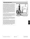
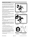
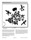
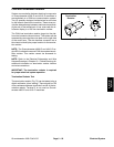
If removal of the TEC controllers is necessary, label the
controllers to make sure they are properly connected to
the machine. The two (2) TEC controllers are visually
identical but they have different software and therefore
cannot be interchanged. The power mount (item 5 in
Fig. 64) can be separated from the operator platform
and carefully lifted from the platform to access the con-
troller f asteners.
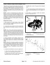
NOTE: The T EC controllers used on the Groundsmas-
ter 4000--D and 4010--D are matched for correct ma-
chine operation. If either of these components are
replaced for any reason, system software needs to be
reprogrammed by your Toro Distributor.
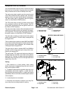
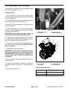
IMPORTANT: Before performing any welding on
your Groundsmaster, disconnect both positive and
negativebatterycables fromthebattery,disconnect
the w ire harness connector from both of the TEC
controllers and disconnect the terminal connector
from the alternator. Also, disconnect and remove
the engine ECU from the machine before welding.
These steps will prevent damage to the machine
electrical system.
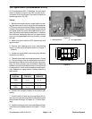
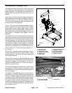
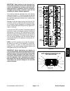
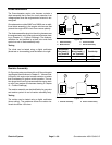
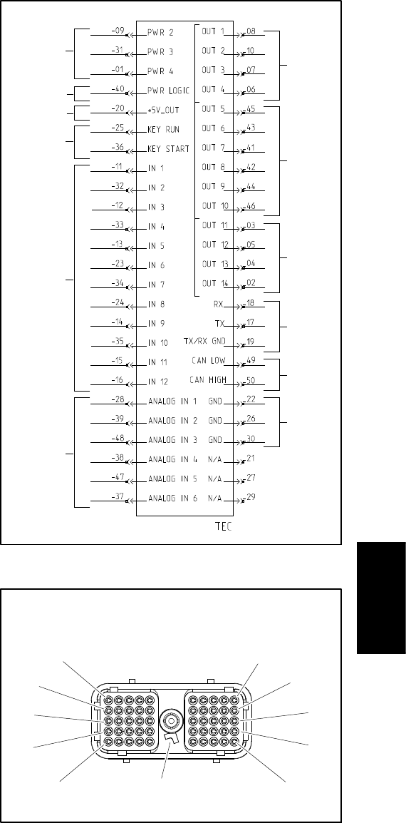
Figure 66
12VPOWER
(7.5AFUSES)
12VLOGIC
IGNITION
SWITCH
INPUTS
DIGITAL
INPUTS
(OPEN/
ANALOG
INPUTS
POWER
(2AMPFUSE)
COMM
PORT
CANBUS
CLOSED)
OUTPUTS
(PWR 2)
GROUND
(VARIABLE)
OUTPUTS
(PWR 3)
OUTPUTS
(PWR 4)
VOLTAGE
OUT
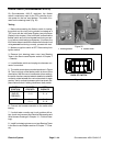
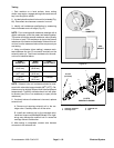
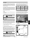
Figure 67
WIRE HARNESS CONNECTOR FOR
TEC CONTROL LERS
11
1
21
31
41
10
50
40
30
20
POSITION
NOTE TAB
Electrical
System