


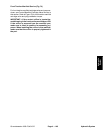

Groundsmaster 4000--D/4010--D Hydraulic SystemPage 4 -- 107
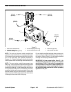
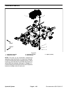
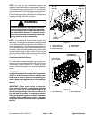
Removal (Fig. 74)
1. Read the General Precautions for Removing and
Installing Hydraulic System Components at the begin-
ning of the Service and Repairs section of this chapter.
2. To prevent contamination of hydraulic system during
manifoldremoval, thoroughlyclean exteriorof combina-
tion manifold and fittings.
3. Label all wire harness connectors that attach to
solenoidcoils oncombinationmanifold.Disconnect wire
harness connectors fromsolenoid coilson thecombina-
tion manifold.
4. Disconnect hydraulic lines from combination man-
ifold and put caps or plugs on open hydraulic lines and
fittings.Label disconnectedhydrauliclines forproper re-
assembly.
NOTE: The combination manifold has three (3) studs
on the bottom surface of the manifold used for securing
themanifoldtothemachine.
5. Remove combination manifold from the frame using
Figure 74 as a guide.
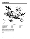
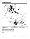
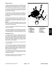
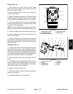
6. If hydraulic fittings are to be removed from manifold,
mark fitting orientation to allow correct assembly (Fig.
75). Remove fittingsfrom manifold and discardO--rings.
Installation (Fig. 74)
1. If fittings were removed from manifold, lubricate and
place new O--rings onto fittings. Install fittings into man-
ifold openings using marks made during the removal
process to properly orientate fittings. Tighten fittings
(see Hydraulic Fitting Installation in the General Infor-
mation section of t his chapter).
2. Install combination manifold to the frame using Fig-
ure74asaguide.
3. Remove caps and plugs from fittings and hydraulic
lines. Using labels placed during manifold removal,
properly connect hydraulic lines to manifold (see Hy-
draulic Hose and Tube Installation in the General Infor-
mation section of t his chapter).
4. Using labels made duringmanifoldremoval, connect
wire harness connectors to the solenoid coils on the
combination manifold.
5. Make surehydraulic tank isfull. Addcorrect oil if nec-
essary before returning machine to service.
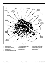
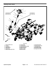
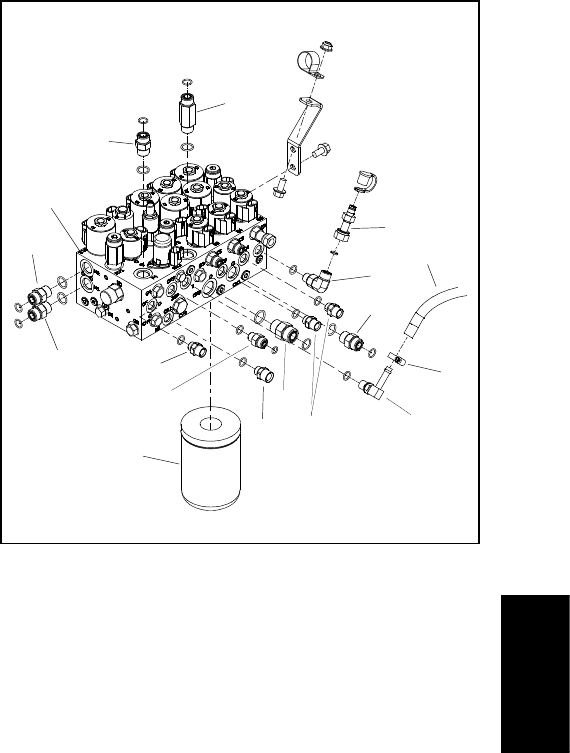
1. Manifold
2. Straight fitting
3. Straight fitting
4. Straight fitting
5. Oil filter
6. Straight fitting
7. Straight fitting
8. Straight fitting
9. Barbed 90
o
fitting
10. Hose clamp
11. Hose
12. 90
o
fitting
13. Test nipple
14. Straight fitting
Figure 75
2
3
6
8
9
10
11
14
1
5
7
12
4
2
2
2
13
Hydraulic
System