


Groundsmaster 4000--D/4010--DHydraulic S ystem Page 4 -- 102
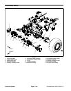
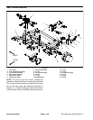
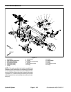
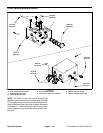
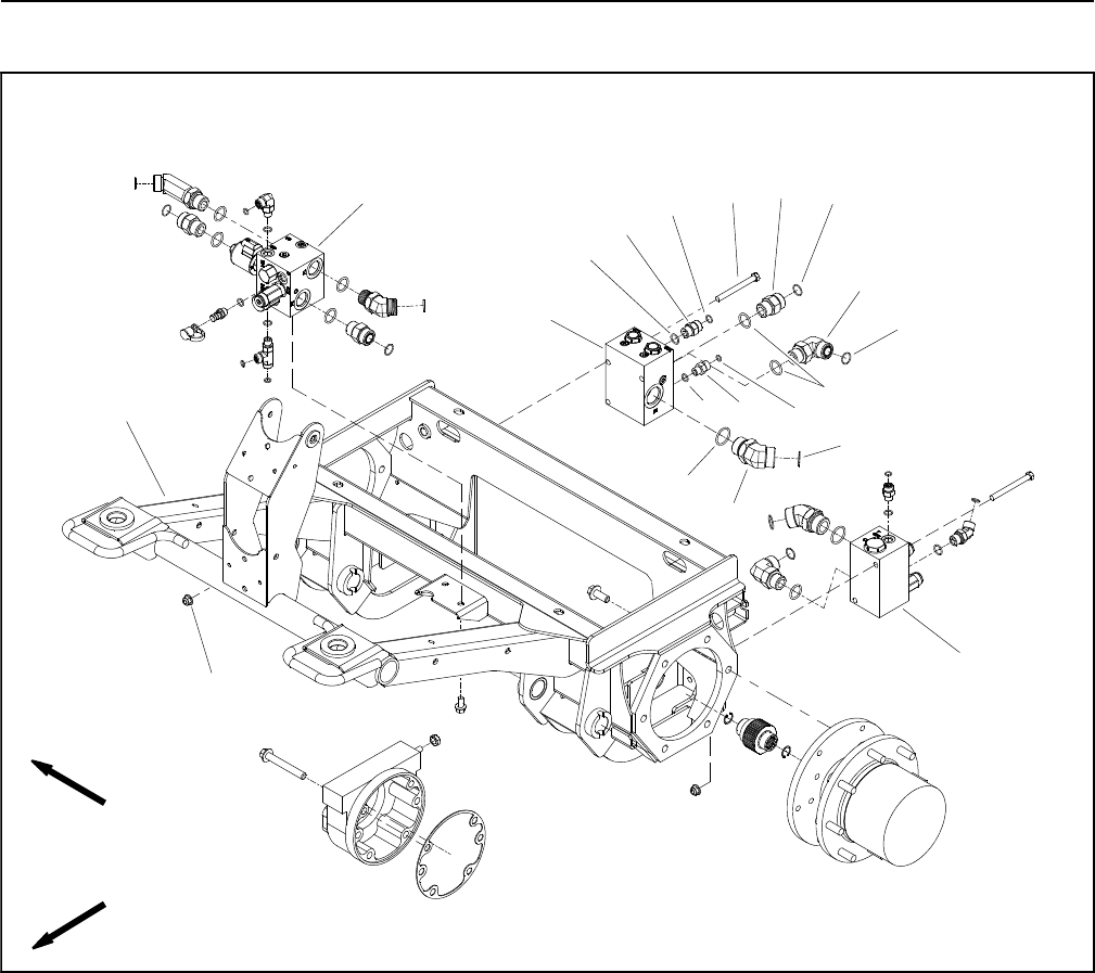
Front Traction Manifold
1. Front frame
2. PTO manifold (center deck)
3. Rear traction manifold
4. Front traction manifold
5. Cap screw (2 used)
6. Flange nut (2 used)
7. O--ring
8. Check fitting
9. O--ring
10. Hydraulic straight fitting
11. O--ring
12. 90
o
hydraulic elbow
13. O--ring
14. O--ring
15. Check adapter
16. O--ring
17. O--ring
18. 45
o
hydraulic elbow
19. O--ring
Figure 72
FRONT
RIGHT
2
3
6
8
9
10
11
13
1
5
7
12
14
15
16
17
18
19
4
11
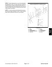
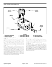
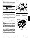
NOTE: The ports on the front traction manifold are
marked for easy identification of components. Example:
P1 is the gear pump connection port and HFD is the loc-
ation for the flow divider valve(see HydraulicSchematic
in Chapter 10 -- Foldout Drawingsto identify the function
of the hydraulic lines and cartridge valves at each mani-
fold port).