


Groundsmaster 4000--D/4010--D Hydraulic SystemPage 4 -- 139
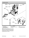
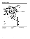
Removal (Fig. 105)
1. Park machine on a level surface, lower cutting
decks, stop engine, apply park ing brake and remove
key from the ignition switch.
2. Read the General Precautions for Removing and
Installing Hydraulic System Components at the begin-
ning of the Service and Repairs section of this chapter.
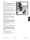
3. To prevent contamination of hydraulic system during
lift cylinder removal, thoroughly clean exterior of cylin-
der and fittings.
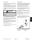
WARNING
Make sure that side cutting deck is fully lowered
before loosening hydraulic lines from side deck
lift cylinder. Ifdeck isnot fullyloweredas hydrau-
lic lines are loosened, deck may drop unexpect-
edly.
NOTE: To easeinstallation,label thehydraulic hosesto
show their correct position on the lift cylinder.
4. Disconnect hydraulic hoses from lift cylinder.
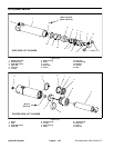
5. Remove shoulder screw and flange nut that secure
the pin assembly (item 4) to the lift arm. Remove pin as-
sembly from lift arm and cylinder rod clevis.
6. Remove lock nut and flat washer from the cylinder
pin(item 7). Removecylinderpin withspringpin fromthe
frame and cylinder barrel clevis.
7. Remove lift cylinder from machine.
8. If hydraulic fittings are to be removed from lift cylind-
er,mark fitting orientationto allowcorrect assembly. Re-
move fittings from cylinder and discard O--rings.
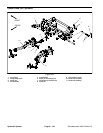
Installation (Fig. 105)
1. If fittings were removed from lift cylinder, lubricate
and place new O--rings onto fittings. Install fittings into
cylinder port openings using marks made during the re-
moval process to properly orientate fittings. Tighten fit-
tings (see Hydraulic Fitting Installation in the General
Information section of this chapter).
2. Position cylinder barrel clevisto frame andinsert cyl-
inder pin (item 7) through the frame and cylinder barrel
clevis. Secure pin with flat washer and lock nut.
3. Insert pin assembly (item 4) through the lift arm and
cylinder rod clevis. Secure pin assembly to lift arm with
shoulder screw and flange nut.
4. Attach hydraulic hoses to lift cylinder (see Hydraulic
Hose and Tube Installation in the General Information
section of this chapter).
5. Fill reservoir with hydraulic fluid as required.
6. After installation is completed, operate lift cylinder t o
verify that lift cylinder, hydraulic hoses and fittings are
not contacted by anything.
Hydraulic
System