


Groundsmaster 4000--D/4010--D Hydraulic SystemPage 4 -- 117
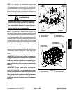
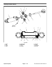
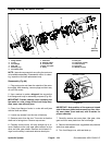
Removal (Fig. 83)
1. Park machine on a level surface, lower cutting
decks, stop engine, apply park ing brake and remove
key from the ignition switch.
2. Read the General Precautions for Removing and
Installing Hydraulic System Components at the begin-
ning of the Service and Repairs section of this chapter.
3. To prevent contamination of hydraulic system during
cylinder removal, thoroughly clean exterior of cylinder
and fittings.
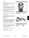
NOTE: To easeinstallation,label thehydraulic hosesto
show their correct position on the steering cylinder.
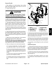
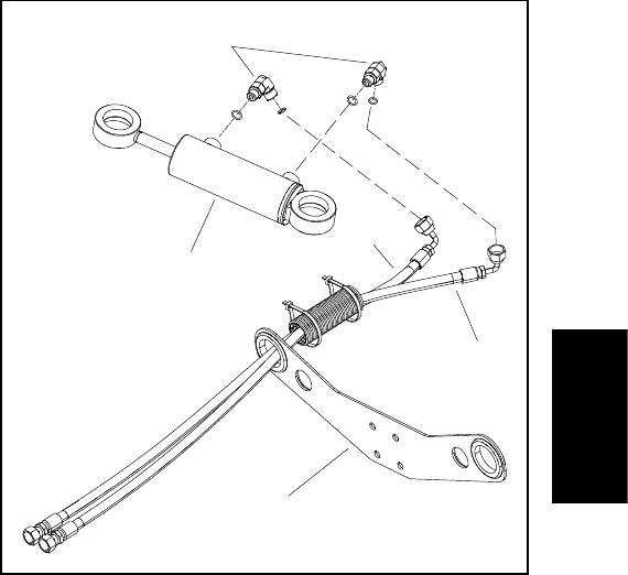
4. Remove hydraulic hoses from steering cylinder (Fig.
84).
5. Remove cotter pins, slotted hex nuts, axle washer
and ball joint spacer from the threaded ends of ball
joints.Remove steering cylinder with balljoints from ma-
chine.
6. If hydraulic fittings are to be removed from steering
cylinder, mark fitting orientation to allow correct assem-
bly. Remove fittings from cylinder and discard O--rings.
7. If needed, remove ball joints from steering cylinder.
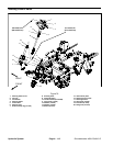
Installation (Fig. 83)
1. If removed, install ball joints into steering cylinder.
2. If fittings were removed from steering cylinder, lubri-
cate and place new O--rings onto fittings. Install fittings
intoport openingsusing marksmade during the removal
process to properly orientate fittings. Tighten fittings
(see Hydraulic Fitting Installation in the General Infor-
mation section of t his chapter).
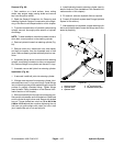
3. Slide ramend ball joint throughhole on steering arm.
Secure with axle washer and hex slotted nut. Slide fixed
end of cylinder through holeon axle. Secure with slotted
hex nut. Torque slotted hex nuts from 79 to 84 ft--lbs
(108 to 113 N--m) and then continue tightening the nut
until hex nut groove aligns with cotter pin hole in b all
joint. Install cotter pin to nut and ball joint.
4. Install hydraulic hoses to steering cylinder (see Hy-
draulic Hose and Tube Installation in the General Infor-
mation section of this chapter).
5. Fill reservoir with new hydraulic fluid as required.
6. Properly fill hydraulic system (see Charge Hydraulic
System in this section).
7. After assembly is completed, operate steering cylin-
derto verifythat hydraulic hoses and fittingsare notcon-
tacted by anything.
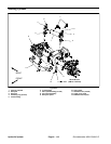
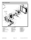
1. Steering cylinder
2. Hydraulic hose
3. Hydraulic hose
4. 90
o
hydraulic fitting
5. Bulkhead mount plate
Figure 84
2
4
3
5
1
Hydraulic
System