


Groundsmaster 4000--D/4010--D Page 5 -- 39 Electrical System
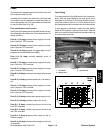
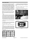
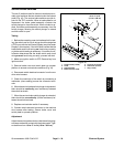
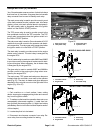
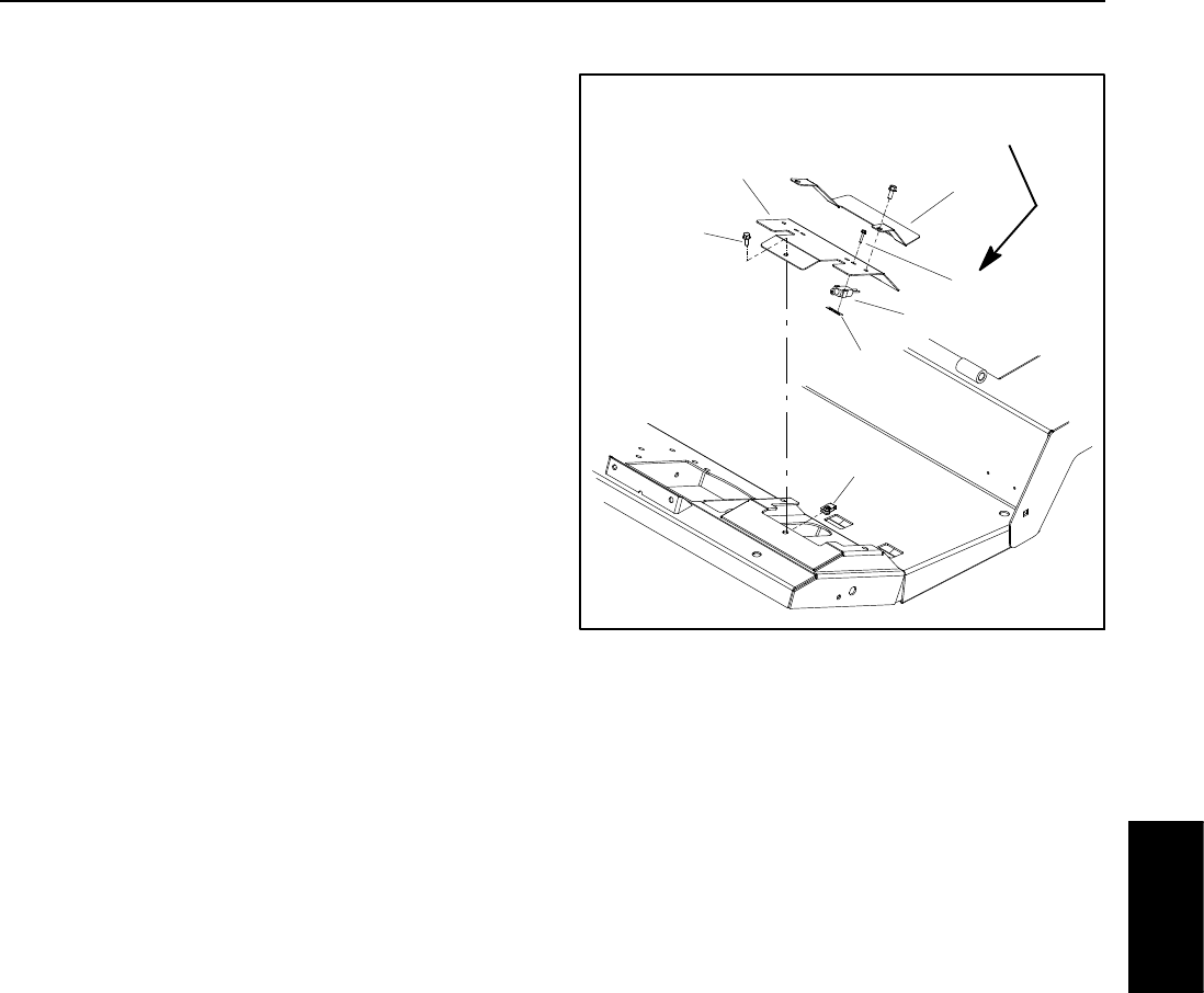
Service Brake Switches
Thetwo(2) switchesused fortheservicebrakesare nor-
mally open switches that are located under the footrest
panel (Fig. 43). The service brake switches provide in-
puts for the TEC controller. When a brake pedal is not
depressed, the brake pedal assembly contacts the
switch plunger to close the switch. When a brake is ap-
plied, the b rake pedal assembly moves away from the
switch plunger, allowing the switch plunger to extend
andtheswitchtoopen.
Testing
1. Before disconnecting a service brake switch for test-
ing, the switch and its circuit wiring should be tested as
a TEC input with the InfoCenter Display (see InfoCenter
Display inthis chapter).If the InfoCenter verifiest hat the
brake switch and circuit wiring are functioning correctly,
nofurtherswitch testing isnecessary.I f, however, theIn-
foCenter determines that the brake switch and circuit
wiring are not functioning correctly, proceed with test.
2. Make sure ignition s witch is OFF. Remove key from
ignition switch.
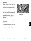
3. Remove brake cover and switch plate on operator
platform to access service brake switches (Fig. 43).
4. Disconnect switch electrical connector from the ma-
chinewireharness.
5. Check the continuity of the switch by connecting a
multimeter (ohms setting) across the connector termi-
nals.
6. Whenthe servicebrakeswitch plunger isdepressed,
there should be continuity (zero resistance) between
the switch terminals.
7. When the service brake switch plunger is extended,
there should be no continuity (infinite resistance) be-
tween the switch terminals.
8. Replace service brake switch if necessary.
9. Connect switch electrical connector to the machine
wire harness after testing. Secure brake cover and
switchplatetooperatorplatform.
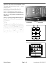
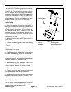
Adjustment
Adjust the service brake switch so that the switch plung-
er always makes full contact with the brake pedal. Tight-
en fasteners from 13 to 17 in-- lb (1.5 to 1.9 N--m).
1. Flange screw ( 3 used)
2. Cover
3. Switch bracket
4. Brake switch (2 used)
5. Screw (2 per switch)
6. Switch nut (2 used)
7. Clip (3 used)
Figure 43
13 to 17 in--lb
(1.5 to 1.9 N--m)
1
3
5
2
4
6
7
Electrical
System