


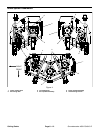
Groundsmaster 4000--D/4010--D Cutting DecksPage 8 -- 11
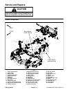
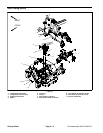
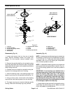
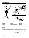
Removal (Fig. 9)
1. Park machine on a level surface, lower cutting deck,
stop engine, engage parking brake and remove key
from the ignition switch.
2. Remove deck covers from top of cutting deck.
CAUTION
Be careful when removing idler spring. The
spring is under heavy load and may cause per-
sonal injury.
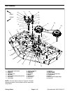
3. Use spring hook tool to unhook the idler spring (item
15) from the adjusting screw (item 4).
4. Remove drive belt(s) from deck pulleys.
5. Loosen flange nuts (item 11) that secure idler stop
bolt (item10) to cuttingdeck to allowclearance between
idler a rm and stop bolt.
6. Remove idler components as needed using Figure
9 as a guide. Note location of washers, idler spacer and
screw as idler assemblies are being removed.
Installation (Fig. 9)
1. Install removed idler components using Figure 9 as
a guide.
A. Make sure that one (1) thrust washer (item 19) is
placed above and below the idler arm. Location of
additional washer (item 22) depends on whether the
idlerpulleymountson thebottomside ofthe idlerarm
or on the top of the idler arm.
B. Secure idler a rm assembly to cutting deck with
retaining ring.
C. Ifidler stop bolt(item 10)was removedfromdeck,
makesure thatit is installed in the holethat allowsthe
stop bolt head to align with the idler arm.
2. Install drive belt to pulleys.
CAUTION
Be careful when installing the idler spring. The
spring is under heavy load and may cause per-
sonal injury.
3. Use spring hook tool to attach the idler spring (item
15) onto the adjusting screw (item 4) and shoulder bolt
on idler arm.
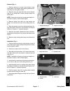
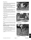
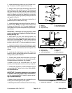
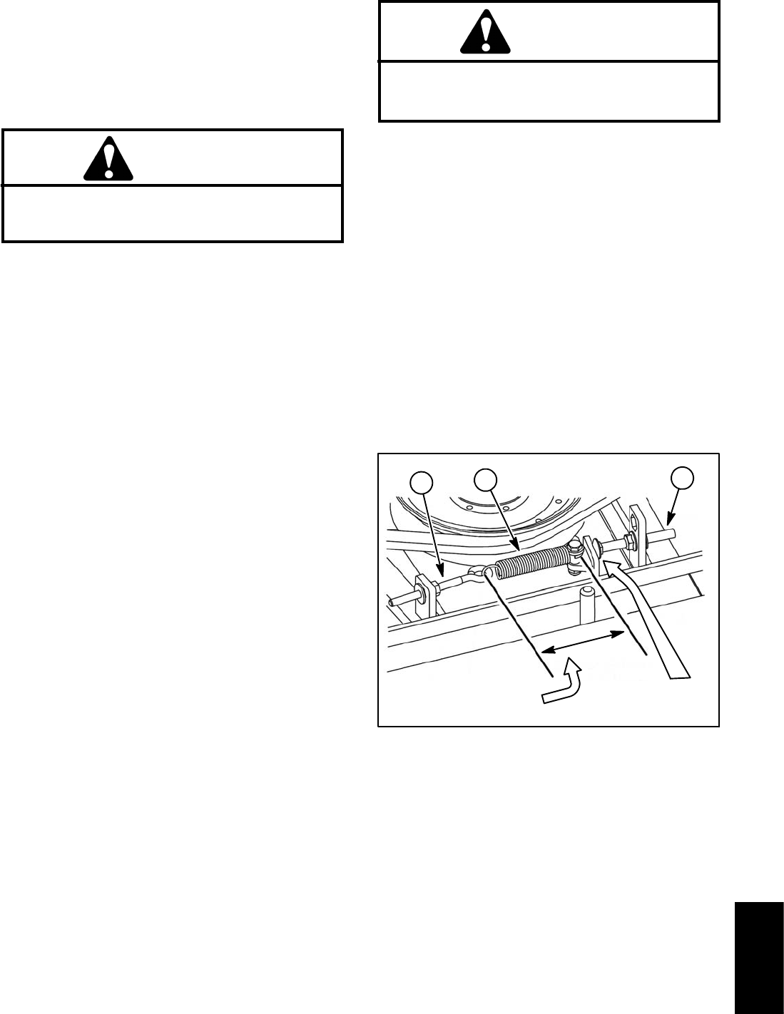
4. With the idler arm tensioning the drive belt, the idler
spring hook to hook length should be from 3.250” to
3.750” (82.6to 95.2 mm) (Fig.10).Ifnecessary,discon-
nect spring and change position of adjusting screw.
When idler spring is the correct length, tighten second
flange nut to secure idler adjustment.
5. Adjust location of idler stop bolt so that theclearance
between idlerarm andidler stop bolthead isfrom 0.125”
to 0.185” (3.2 to 4.6 mm) (Fig. 10).
6. Lubricate idler arm grease fitting.
7. Install deck covers to cutting deck.
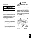
Figure 10
3.250” to 3.750”
(82.6 to 95.2 mm)
0.125” to 0.185”
(3.2 to 4.6 mm)
1. Idler stop bolt
2. Idler spring
3. Adjusting screw
1
2
3
Cutting
Decks