


Groundsmaster 4000--D/4010--DHydraulic S ystem Page 4 -- 134
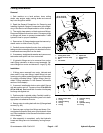
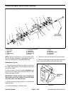
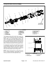
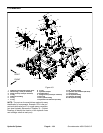
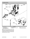
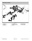
PTO Manifold
1. Hydraulic PTO manifold (center deck)
2. Quick fitting (1 used per manifold)
3. Flange screw (2 used per manifold)
4. O--ring
5. Hydraulic tee fitting
6. O--ring
7. O--ring
8. O--ring
9. Hydraulic adapter
10. Straight fitting
11. Flange screw (2 used per manifold)
12. Dust cap
13. 45
o
hydraulic fitting
14. Hydraulic PTO manifold (LH deck)
15. 90
o
hydraulic fitting
16. Hydraulic PTO manifold (RH deck)
17. Hex head plug
18. 45
o
hydraulic fitting
19. Hydraulic tee fitting
20. 90
o
hydraulic fitting
Figure 101
FRONT
RIGHT
2
3
6
8
9
11
13
1
5
7
12
14
15
16
17
20
4
10
2
2
12
12
9
10
19
18
18
18
18
13
13
4
4
4
4
4
6
6
7
7
7
7
7
8
8
8
8
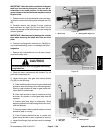
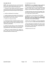
NOTE: The ports on the manifold are marked for easy
identification of components. Example: PRV is the pro-
portional relief valve and P1 is a gear pump connection
port (see Hydraulic Schematic in Chapter 10 -- Foldout
Drawings to identify the function of the hydraulic lines
and cartridge valves at each port).