


Groundsmaster 4000--D/4010--DPage 7 -- 22Chassis
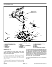
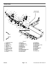
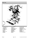
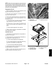
Assembly (Fig. 19)
1. Make surethatall machinecomponents areinstalled
below operator platform before platform is lowered to
frame.
IMPORTANT: Make sure to not damage the electric-
al wireharness orother components while lowering
the operator platform.
2. Carefully lower operator platform and position over
center mounts (item 4) that are installed in the frame.
3. Secure operator platform to machine frame with four
(4) cap screws, flat washers, plain washers and lock
nuts. Torque lock nuts from 95 to 115 ft--lb (129 to 155
N--m).
4. Connect all electrical wire harness connections
between operator platformcomponents and mainframe
locations.
5. On Groundsmaster 4010 machines:
A. Install operator cab to machine.
B. Secure operator cab coolant and air conditioner
hoses in engine compartment with cable ties in loca-
tions noted during disassembly.
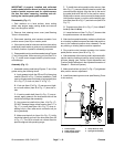
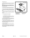
6. Connect both brake cables to brake pedals and op-
erator frame. Adjust brakes so that both pedals have 1/2
to 1 inch (13 to 25 mm) of free travel.
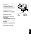
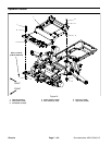
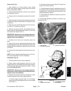
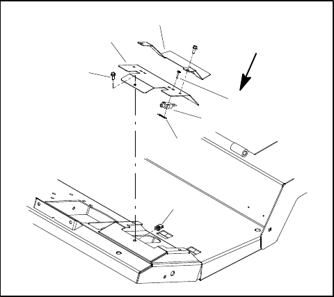
7. Position traction pedal assembly to operator plat-
form and secure with removed fasteners (Fig. 21). Con-
nect machinewire harness connectorto position sensor
on traction pedal assembly.
8. Securesteering tower coversto m achine (seeSteer-
ing Tower in this section).
9. Connect positive battery cable f rom battery terminal
and then connect negative cable to battery (see Battery
Service in the Service and Repairs section of Chapter 5
-- Electrical System).
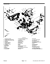
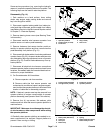
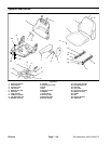
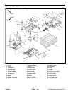
1. Flange screw (3 used)
2. Adjustment cover
3. Switch bracket
4. Brake switch (2 used)
5. Screw (2 per switch)
6. Switch nut (2 used)
7. Clip (3 used)
Figure 23
13 to 17 in--lb
(1.5 to 1.9 N--m)
1
3
5
2
4
6
7