Table of Contents
MTG100 & MTG300 MPEG Generator Service Manual
v
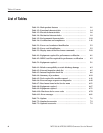
Figure 6-41: System dialog box 6-70. . . . . . . . . . . . . . . . . . . . . . . . . . . . . . .
Figure 6-40: Organization of the device error codes 6-77. . . . . . . . . . . . . .
Figure 9-1: MTG100 and MTG300 block diagram 9–3. . . . . . . . . . . . . . .
Figure 9-2: MTG100 and MTG300 interconnect diagram 9–5. . . . . . . . .
Figure 10-1: Cabinet 10-5. . . . . . . . . . . . . . . . . . . . . . . . . . . . . . . . . . . . . . . .
Figure 10-2: Front panel unit 10-7. . . . . . . . . . . . . . . . . . . . . . . . . . . . . . . . .
Figure 10-3: Internal modules and rear connectors 10-9. . . . . . . . . . . . . . .
Figure 10-4: Hard disk drives 10-11. . . . . . . . . . . . . . . . . . . . . . . . . . . . . . . .
Figure 10-5: Board modules and inner units 10-13. . . . . . . . . . . . . . . . . . . .
Figure 10-6: CPU unit 10-15. . . . . . . . . . . . . . . . . . . . . . . . . . . . . . . . . . . . . . .
Figure 10-7: Power supply unit 10-17. . . . . . . . . . . . . . . . . . . . . . . . . . . . . . .
Figure 10-8: Rack mount 10-19. . . . . . . . . . . . . . . . . . . . . . . . . . . . . . . . . . . .


