MTG100 & MTG300 MPEG Generator Service Manual
4Ć1
Performance Verification
This section provides procedures that verify the performance of the MPEG
generator. These tests confirm performance and functionality when the following
conditions are met:
H The MPEG generator must be operating in an environment that is within the
operating limits described in Table 1-5 on page 1-10.
H The MPEG generator and test equipment must have had a warm-up period of
at least 20 minutes.
Equipment and Test Signals Required
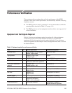
Table 4-1 lists the test equipment required to perform all of the performance
verification procedures. The table identifies examples of recommended
equipment and lists the required precision where applicable. If you substitute
other test equipment for the examples listed, the equipment must meet or exceed
the listed tolerances.
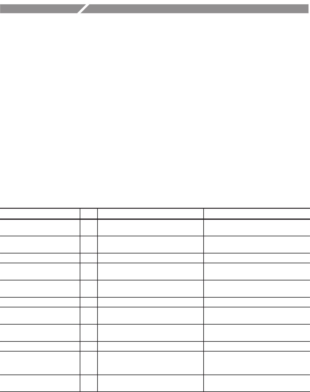
Table 4Ć1: Equipment required for performance verification
Item No. Minimum requirements Recommended equipment
Frequency counter 1 Frequency range: 0.1 Hz to 1250 MHz
Precision: 7 digits or higher
ANRITSU MF 1603A
Signal generator 1 Frequency: 27 MHz ±1 ppm
Amplitude: 0.0 dBm
HP 8648
Oscilloscope 1 Bandwidth: 1 GHz or higher Tektronix TDS784D
MPEG analyzer 1 Real Time Analyzer, Deferred Time Analyzer,
and Data Store Administrator applications
Tektronix MTS205 or MTS215 option SS
75 W to 50 W minimum loss
attenuator
1 Bandwidth: 1 GHz
Amplitude precision: -3 dB
Tektronix AMT75
Probe 1 X1 Tektronix P6101B
BNC cable 1 Impedance: 50 W
Length: 42 inches
Tektronix part no. 012Ć0057Ć01
BNC cable 1 Impedance: 75 W
Length: 42 inches
Tektronix part no. 012Ć0074Ć00
NĆtoĆBNC adapter 1 Tektronix part no. 103Ć0045Ć00
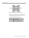
Custom interface cable 1 Type: 9Ćpin, DĆtype (male) - to - 25Ćpin,
DĆtype (male), see Figure 4Ć1
Length:1mto2m(asneeded)
Custom interface cable, see Figure 4Ć1.
Parallel interface cable 1 25Ćpin, DĆtype, twisted pair Tektronix part no. 174Ć3882Ć01,
(supplied with the MPEG generator)


