


Performance Verification
4Ć14
MTG100 & MTG300 MPEG Generator Service Manual
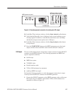
This test confirms that the external clock input (ECL CONTROL input) on the
MPEG generator is functioning correctly. The following equipment and MPEG
test signal is required for this test:
H MPEG test system
H 75 W BNC cable
H Custom 9-pin to 25-pin, D-type interface cable
H test40.trp MPEG test signal
Perform the following procedure to verify that the external clock input
(ECL CONTROL input) on the MPEG generator is functioning correctly:
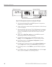
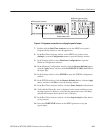
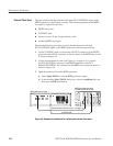
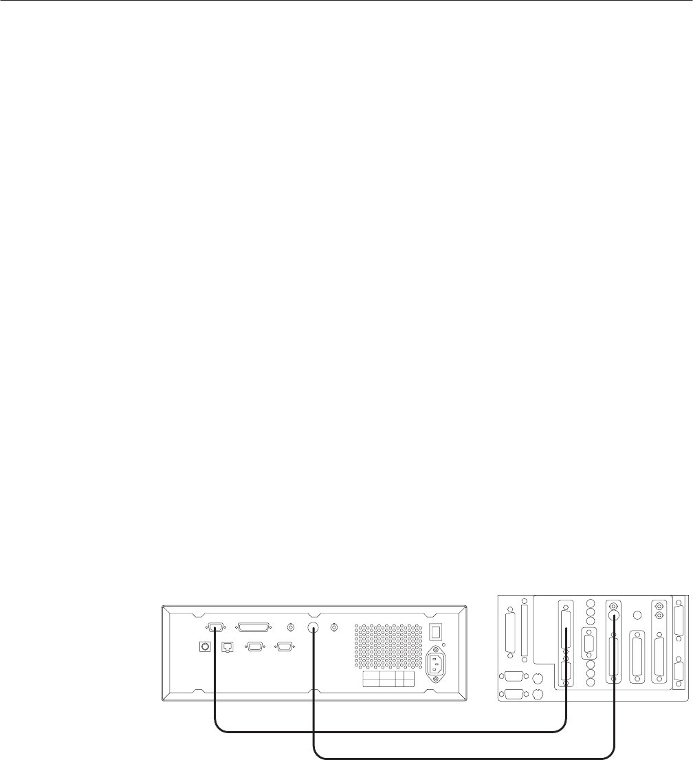
1. Use the 75 W BNC cable to connect the ASI OUT connector on the MPEG
generator to the ASI IN connector on the rear panel of the MPEG test system
as shown in Figure 4-9.
2. Use the custom interface cable (see Figure 4-1 on page 4-2) to connect
the ECL CONTROL connector on the MPEG generator to the ECL
PARALLEL/SERIAL I/O connector on the MPEG test system rear panel as
shown in Figure 4-9.
3. Open the test40.trp file on the MPEG generator.
a. Select Open TS File... from the FILE pull-down menu.
b. In the resulting Select TS File dialog box, select the test40.trp file, and
then press the OK bezel button.
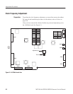
MPEG generator rear panel
75 W BNC cable
Custom interface cable (see Figure 4Ć1 on page 4Ć2)
MPEG test system rear panel
(MTS200 or MTS215 Opt. SS)
Figure 4Ć9: Equipment connections for verifying the external clock input
External Clock Input