


Performance Verification
4Ć8
MTG100 & MTG300 MPEG Generator Service Manual
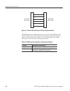
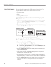
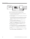
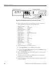
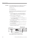
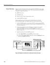
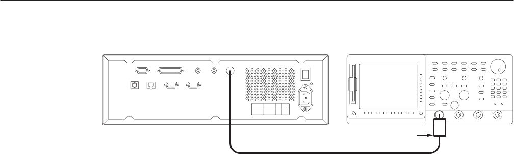
MPEG generator rear panel
75 W BNC cable
Oscilloscope (TDS784D)
75 W to 50 W
minimum loss attenuator
Figure 4Ć5: Initial equipment connection for verifying the SSI output
2. Set the oscilloscope controls as indicated below (only the horizontal axis
setting is different from the setup in the ASI Output test):
Displayed channel CH1. . . . .
Vertical axis 200 mV/div. . . . . . . . . .
Horizontal axis 10 ns/div. . . . . . .
Horizontal position Center. . . .
Record length 500. . . . . . . .
Acquire mode Sample. . . . . . . .
Acquire sequence RUN/STOP button only. . . . .
Trigger mode Auto. . . . . . . . .
Trigger level 0 V. . . . . . . . .
Trigger source CH1. . . . . . . .
Trigger position 50 %. . . . . . .
Trigger slope Rising Edge. . . . . . . . .
Trigger coupling DC. . . . . .
Display style Dots. . . . . . . . .
Input coupling DC. . . . . . . .
Input impedance 50 W. . . . . .
Measure Amplitude. . . . . . . . . . . . .
3. Open the test40.trp file on the MPEG generator.
a. Select Open TS File... from the FILE pull-down menu.
b. In the resulting Select TS File dialog box, select the test40.trp file, and
then press the OK bezel button.
4. Press the START/STOP button on the MPEG generator to start the signal
output of the test40.trp file.
5. Verify that the following LEDs on the MPEG generator’s front panel are
illuminated: PLL, BUFFER, and HDD.
6. Use the oscilloscope to measure that the signal amplitude is within the range
of 720 mV to 880 mV.