Specifications
MTG100 & MTG300 MPEG Generator Service Manual
1Ć7
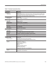
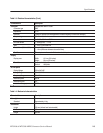
Table 1Ć3: Electrical characteristics (Cont.)
Characteristics Description
External reference input
Connector type BNC
Frequency 27 MHz, 1 ppm recommended.
Input level, typical 800 mV ± 200 mV (pĆp)
Input impedance, typical 50 W (at 27 MHz)
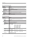
ECL control input
Connector type DĆsub, 9 pin
Frequency 125 kHz to 8 MHz, select parallel output.
1 MHz to 64 MHz, select serial output.
Input level, typical Differential ECL
Termination, typical 110 W, line to line.
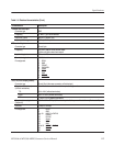
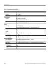
Pin assignment 1 DCLK
2GND
3 PSYNC
4 CHCLKEN
5 Shield
6 DCLK
7GND
8 PSYNC
9 CHCLKEN
ECL/TTL/LVDS output (parallel)
Connector type DĆsub, 25 pin (the same connector as Serial output)
Output level (Output on)
(J310101 and above)
Note: Do not connect the Asserted Low pins for singleĆend use.
TTL 0 V to 2.8 V (without termination)
LVDS 0.8 V to 1.60 V (without termination)
ECL*
-1.8 V to -0.9 V (without termination)
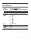
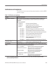
Output resistance, typical
(Output off)
350 W at5VtoGNDpin(When the output is off, the power of the buffer amplifier is cut off.)
Data rate 1 Mbps to 64 Mbps
Pin assignment 1 DCLK
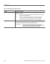
2GND
3to10 DATA7toDATA0
11 DVALID
12 PSYNC
13 Shield
14 DCLK
15 GND
16 to 23 DATA 7 to DATA 0
24 DVALID
25 PSYNC


