


Removal and Installation Procedures
MTG100 & MTG300 MPEG Generator Service Manual
6Ć37
Procedure for Board Modules and CPU Unit
Perform the Access Procedure (on page 6-17) before performing any procedure
in this group. The procedures are presented in the order listed:
H A10 Main Board
H A40 MISC (Power Distribution & Interface) Board
H CPU Unit
H CPU Board
H A20 Interface Board
H LAN Board
H Backplane
1. Assemble equipment and locate modules to be removed:
a. You need a screwdriver with a size Phillips #2
tip (Items 1 and 3).
b. Locate the modules to be removed in the locator diagram Board modules
and CPU unit, Figure 6-4, page 6-15.
2. Orient the instrument: Set the MPEG generator so its bottom is down on the
work surface and its front is facing you.
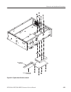
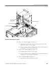
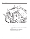
3. Remove the A10 Main Board:
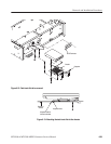
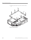
a. Unplug these cables. See Figure 6-18 as a guide.
H The cables from the A20 Interface board at J0602 and J0600.
H The cables from the data hard disk drive at J2100 and J2300.
H The cable from the A40 MISC (Power Distribution & Interface)
board at J0740.
H The cables from the ECL CONTROL connector at J3702 and
ECL/TTL/LVDS OUT connector at J4004.
H The coaxial cables from the SSI OUT connector at J4000, the ASI
OUT connector at J4002 and the EXT 27 MHz REF IN connector at
J3700.
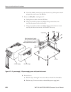
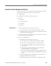
b. Using a screwdriver with a size Phillips #2 tip, remove the six screws
securing the A10 Main board to the chassis.
c. Lift the board up and away from the chassis to complete the removal.
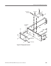
A10 Main Board