


Removal and Installation Procedures
MTG100 & MTG300 MPEG Generator Service Manual
6Ć35
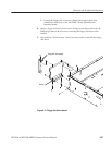
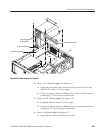
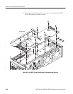
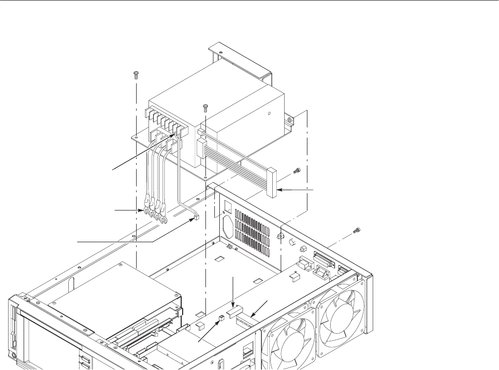
J040
J030
J041
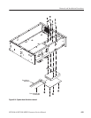
To J041 on A40 board
To J030 on A40 board
To J040 on A40 board
Gray wire goes
to left connector
Figure 6Ć16: Power supply unit removal
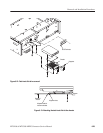
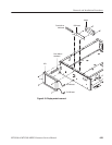
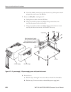
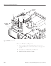
4. Remove the 5 V Power supply: See Figure 6-17.
a. Unplug the two cables at the connectors on the power switch and one
cable at CN1 on the 12 V Power supply.
b. Using a screwdriver with a size Phillips #2 tip, remove the four screws
securing the 5 V Power supply to the bracket.
5. Remove the 12 V Power supply: See Figure 6-17.
a. Unplug the cable from the 5 V Power supply.
b. Using a screwdriver with a size Phillips #2 tip, remove the three screws
securing the 12 V Power supply to the bracket.
6. Remove the Power switch: See Figure 6-17.
a. Unplug the four cables from the power switch.