


PPG Application Design
20 PT Program Generator (PPG) v5.0
The virtual display maintains the latest lines of data once all lines of the virtual
display are full. The oldest lines of data are “pushed off the top” as new data is
added at the bottom.
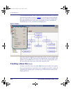
Defining Program Flow
After you create all the nodes, connect the program pieces together using Link
Nodes
to define the flow of the program.
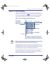
Links are shown on the PPG display with arrows which point from one step to
the next. Some nodes will have multiple entry and exit points. For example, a
Copy node can have either one or two exit points. You may choose to have
your application go to a
Display node if an error occurs or, if the copy opera-
tion is successful, to continue on to a
Menu node.
For information on the mechanics of creating, modifying and deleting Links,
refer to
Links on page 73.
Refer to
Data on page 43 for a brief overview of data types and Links to each
type’s description. For more detailed information on managing program data
or to specify a
Data File, Field, Template, or Register, refer to Managing Data on
page 77.
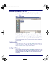
Sending and Receiving Files
The final step in using PPG is to transfer the applications you have created to
the Falcon PT40. Refer to
PT40 Communication on page 89 for more information
on sending and receiving files.
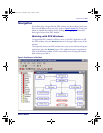
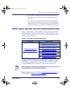
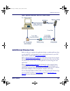
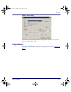
Figure 5 on page 21 is a flow chart showing the application generation, data flow,
file transfer process used when you create custom files with PPG
and down-
load them to your PSC Falcon PT40 from a PC.
2342.book Page 20 Thursday, July 22, 2004 8:35 AM