


Delay Relay Output Board Option Hydrastep 2468CB and 2468CD Manual
3b-14 24685034
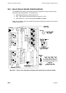
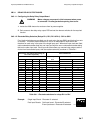
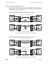
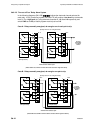
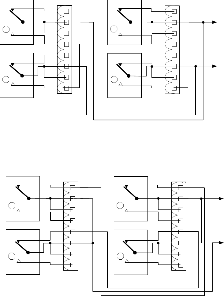
3b.3.2.5 ‘Two out of Four’ Relay Alarm System
In the following diagrams (5A & 5B)
indicate the electrode channel selected for
each relay. A fully functioning system (NO FAULTS) will perform a low level trip at electrode
level 3. For a high level trip, using electrode channels 11, 12, 9 and 10 respectively and
switch SW5 set for ES, a healthy system would trip at level 10.
Case A - Relays normally energised, de-energise one in each pair to trip
(Relays shown in de-energised state)
1
4
3
2
5
8
7
6
(Switch SW5 is set to EW for low-level alarms and set to ES for high-level alarms)
1
4
3
2
5
8
7
6
To alarm
annunciator
or tripping
device
RL 1
RL 2
RL 2
RL 1
PL 2
PL 2
Odd electrodes
(RH input board)
Even electrodes
(LH input board)
3
1
4
2
Alarm off when contacts open
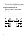
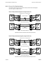
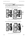
Case B - Relays normally energised, de-energise one pair to trip
(Relays shown in de-energised state)
1
4
3
2
5
8
7
6
(Switch SW5 is set to EW for low-level alarms and set to ES for high-level alarms)
1
4
3
2
5
8
7
6
To alarm
annunciator
or tripping
device
RL 1
RL 2
RL 2
RL 1
PL 2
PL 2
Odd electrodes
(RH input board)
Even electrodes
(LH input board)
3
1
4
2
Alarm off when contacts open